1066
Feasibility Study for Wireless RF Coil: Wireless transfer of 8ch MR received data using body array coil and system clock1MRI Systems Development Department, CANON Medical Systems Corporation, Kawasaki, Japan, 2CANON Medical Systems Corporation, Kawasaki, Japan, 3Platform Technology, Canon Medical Research USA Inc., Vernon Hills, IL, United States, 4MRI Systems, Canon Medical Research USA Inc., Mayfield Village, OH, United States, 5Digital Business Platform Development Headquarters, Canon Inc., Tokyo, Japan
Synopsis
Keywords: RF Arrays & Systems, RF Arrays & Systems, wireless
We prototyped a new acquisition board (NAB) equipped with wireless signal transmission modules, and connected it to the reception RF coil and the scanner system. The configuration enabled that the transmission of the 8-ch reception signal data from the RF coil and the system clock was carried out between boards wirelessly. Finally, two-dimensional SE images were obtained without deterioration in image quality.Introduction
With the advancement of MRI equipment, the number of receiving RF coils has increased, and a 128-ch coil was studied for research1. As a result, the receiving RF coil cable has become a composite cable that bundles many coaxial cables, and it is accompanied by baluns to prevent temperature rise due to RF, making it thick and difficult to handle. Elimination of the cables from RF coils has long been attempted, with wireless being the most attractive approach, and many papers have been published and reviewed by Nohaba2.In this study, we prototyped a new acquisition board (NAB) equipped with wireless signal transmission modules and connected it to the RF coil and system sides, respectively. Then, the SE sequence was executed, and wireless transmission of the data of the 8ch reception signals of the reception RF coil and the system clock was carried out between boards. And two-dimensional SE images were obtained without deterioration in image quality.
Methods
- Experiment systemExperiments were performed on the Canon 3T system, which configuration is shown in figure 1. 3T 16-ch body coil was connected to the interface box and 8-ch signals were inputted to NAB. A PIN-diode drive signal is supplied to the coil along with the preamp power line through the interface box. The coil-side NAB performs the following processing.
1) Analog data processing [amplifying of 8-ch signals of body coil]
2) Digitizing data (8-ch, 100MHz sampling, 16bit) , decimation and down-conversion to 2MHz (Xilinx Zynq)
3) Transmitting data via Wi-Fi [WLAN 802.11ac MIMO 2x2, 5GHz band]
4) Receiving the system clock [2.4GHz band, demodulation of clock sent]
The system side NAB performs the following processing and sends the data to the system.
1) Receiving data through Wi-Fi
2) Transmitting the system clock [2.4GHz band, clock transmission by phase continuous frequency modulation]
DC power and sequence trigger signal were sent through wired connections.
- Wireless environment evaluation in a shielded room
The wireless environment in the shield room was evaluated and the attenuation characteristics were confirmed.
- Data transmission
Data sampled at 8-ch and 16bit were down-converted to 2MHz and transmitted through the prototype Wi-Fi module (data rate: 256Mbps).
- Clock transmission
Frequency modulation was adopted to satisfy the radio laws of Japan, the United States, and Europe. In the clock transmission module, a binary frequency modulated signal with a center frequency of 2.4 GHz was transmitted using a carrier based on a 10 MHz system clock signal. After removing the jitter, a 10 MHz clock that is frequency-synchronized with the system clock signal is generated.
Non-magnetic materials were selected as much as possible in both transmission modules.
Results and Discussion
Evaluation of individual modules and overall evaluation combined with the MRI system was performed.- Wireless environment evaluation in a shielded room
We measured the throughput of data transmission (Figure 2). A dipole antenna and a small antenna (Planar inverted-F antenna) were used. It was confirmed that a gain of about -60dB or more can be secured for both antennas for transmission power of 0dBm.
- Wi-Fi module
The transmission power is 10dBm. The transfer rate measured using the reference board was around 480Mbps as UDP/IP throughput. This is sufficient for data transfer in this experiment.
- Clock transmission & receiving module
The modulated signal from the clock transmission module was transmitted wirelessly to the receiving module via an antenna, and the jitter of the regenerated clock was evaluated. The jitter in the band from 12 kHz to 20 MHz was 675.3fs under the following condition [Modulation: 5MHz/ 10Mbps, Center frequency: 2420MHz, Output: 10dBm, Attenuation between antennas: -35dB].
- Imaging test using the body array coil
The body array coil was set on a cuboid phantom containing mineral oil, and 8-ch signals of this body coil were used (figure 3, dotted red frame). SE images were acquired for the central AX section in the Z direction (Figure 3). Compared with conventional images, there was no deterioration in images obtained by wireless data transfer and clock transfer (Figure 4). In this experiment, communication was possible both through the direct path and through the indirect path. When there is an obstacle between the clock antennas during data acquisition, the clock may shift or fall off. In actual use, it is necessary to arrange the antennas on paths that do not interfere with such obstacles and to keep the distance between antennas as close as possible. On the other hand, when the clock antenna was periodically moved simulating the effect of breathing, the clock did not lose its lock, and the motion artifacts were not significant but observed (Figure 5) 3. This suggests the possibility of avoiding this by gated imaging.
Conclusion
We prototyped an 8-ch data acquisition /processing board equipped with modules for wireless data and clock transfer and the data of the 8-ch receiving signal of the body coil and the system clock were wirelessly transmitted between the boards. 2D SE images can be acquired without image quality degradation.Acknowledgements
No acknowledgement found.References
1. Christopher J. Hardy, Randy O. Giaquinto, AAS, Joseph E. Piel, BS, Kenneth W. Rohling, AAS, Luca Marinelli, Daniel J. Blezek, Eric W. Fiveland, MS, Robert D. Darrow, and Thomas K.F. Foo. 128-Channel Body MRI with a Flexible High-Density Receiver-Coil Array. J Magn Reason Imaging 2008; 28: 1219-1225.
2. Lena Nohava, Jean-Christophe Ginefri, Georges Willoquet, Elmar Laistler, Roberta Frass-Kriegl. Wireless RF Coils. Frontiers in Physics 2020; Vol 8, Article 11.
3. Jonathan Y Lu1, Pascal Stang2, Fraser Robb3, John Pauly1, and Greig Scott1. Wireless Clock Transfer for MRI Phase Correction. Proceedings of the International Society for Magnetic Resonance in Medicine (2017). p. 2692.
Figures
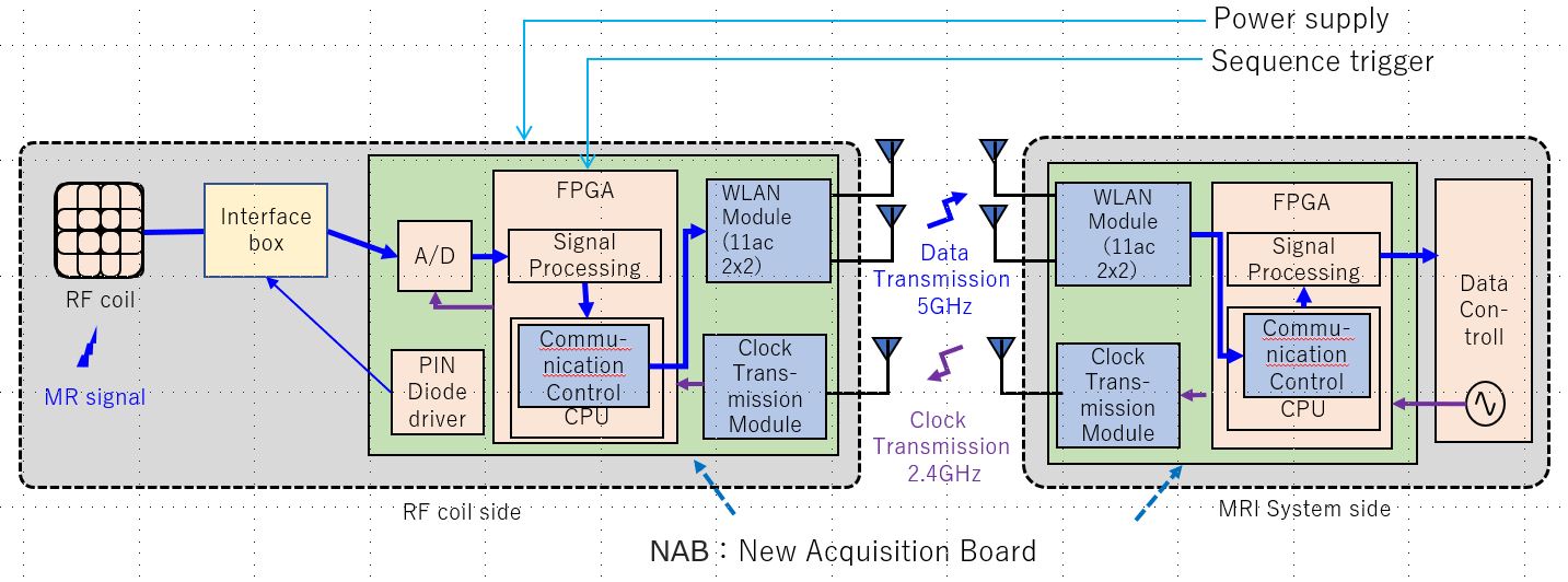
Figure 1 Experimental system configuration
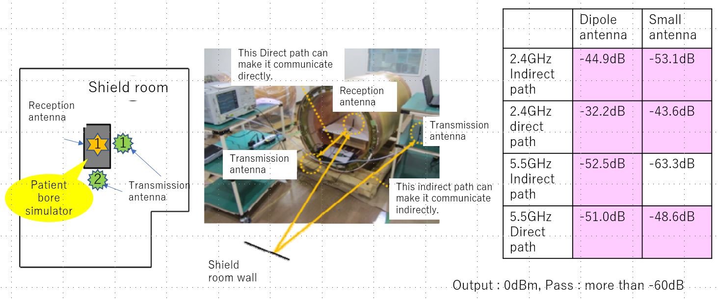
Figure 2 Wireless environment evaluation in a shield room
A gradient coil cylinder simulating the patient's bore was placed, the receiving antenna was placed in the center of the bore, and the transmission antenna for the direct path was placed on the axis of the cylinder, and the antenna for indirect path on the side of the cylinder.
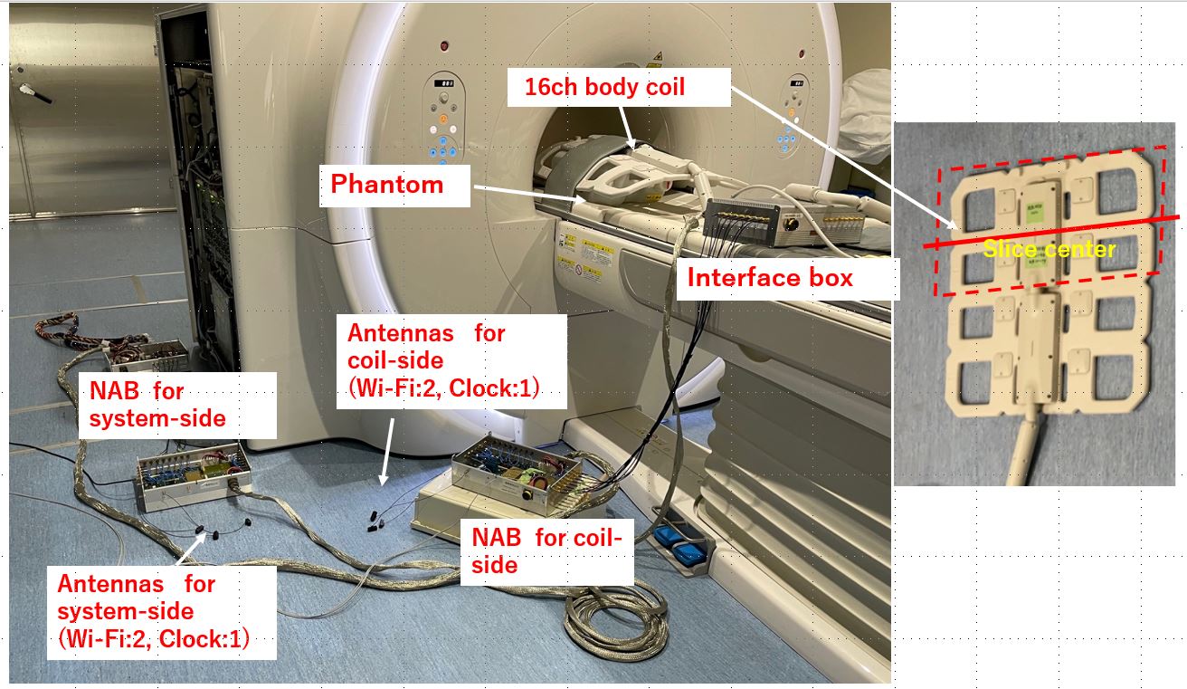
Figure 3 System setup for image evaluation
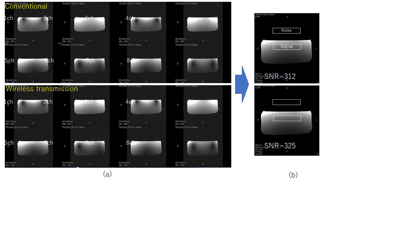
Figure 4 Phantom images: comparison between conventional case (wired) and wireless transmission case
(a) 8ch images from 8ch coils (Each image was generated by combining the signals of eight coils.) (b) Combined images for each case. The SNR was measured in the dotted region.
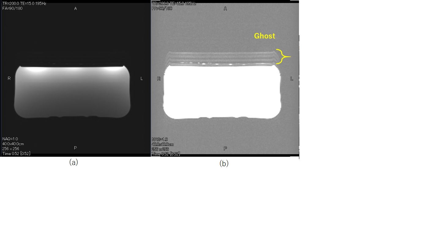
Figure 5 Phantom images: effect of antenna moving (2Hz, Δ5cm)
The space between clock antennas is 30cm.
(a) Normal brightness correction
(b) Ghost enhancement brightness correction
(The peak ghost signal is about 1/80 compared with the phantom signal.)