1061
Evaluation of Coaxial Dipole Antennas as Transceiver Elements of Human Head Array for Ultra-High Field MRI at 9.4T1High-field Magnetic Resonance, Max Planck Institute for Biological Cybernetics, Tuebingen, Germany, 2Department for Biomedical Magnetic Resonance, University of Tübingen, Tuebingen, Germany
Synopsis
Keywords: RF Arrays & Systems, RF Arrays & Systems
Arrays of dipole antennas were recently introduced as transceiver RF coils for human head imaging at UHF as a simple and robust alternative to loop arrays. Due to the head size, dipoles should be significantly shorter than λ/2 at working frequency. Short dipoles suffer from high SAR and insufficient brain coverage. In addition, since head arrays are usually placed on rigid holders, the resonance frequency of dipoles change drastically with head size variation. In this work, we developed a coaxial dipole array for human head imaging at 9.4T. The developed coil provides whole-brain coverage, low SAR, and low frequency variation.Purpose
To evaluate the coaxial dipole antennas as transceiver elements of a human head array at 9.4T.Introduction
Arrays of dipole antennas were recently introduced as transmit or transceiver RF coils for human head imaging at ultra-high field (UHF) (i.e., larger than 7T) (1,2) as a simple and robust alternative to loop arrays. Due to the sample size, dipole antennas for head imaging should be significantly shorter than λ/2 at working frequency. Such short dipoles (around 17 cm) suffer from high SAR and insufficient brain coverage due to the “triangular” current distribution with a relatively sharp peak at the center (3). In addition, since head arrays are usually placed on rigid holders, the resonance frequency of dipoles could change drastically with the head size variation. To overcome these issues, previously we developed a novel antenna design by folding ends of the common straight dipole and moving them away from the subject, i.e. a so-called folded-end dipole (3,4,5). This design, however, has a disadvantage because folded ends require additional space inside the coil housing. Another method to flatten and extend the current distribution longitudinally is using coaxial dipoles in combination with lumped elements (6). In this work, we developed a 9.4T coaxial human head transceiver dipole array. To our best knowledge, this is a first example of using coaxial dipoles for human head MRI at UHF.Methods
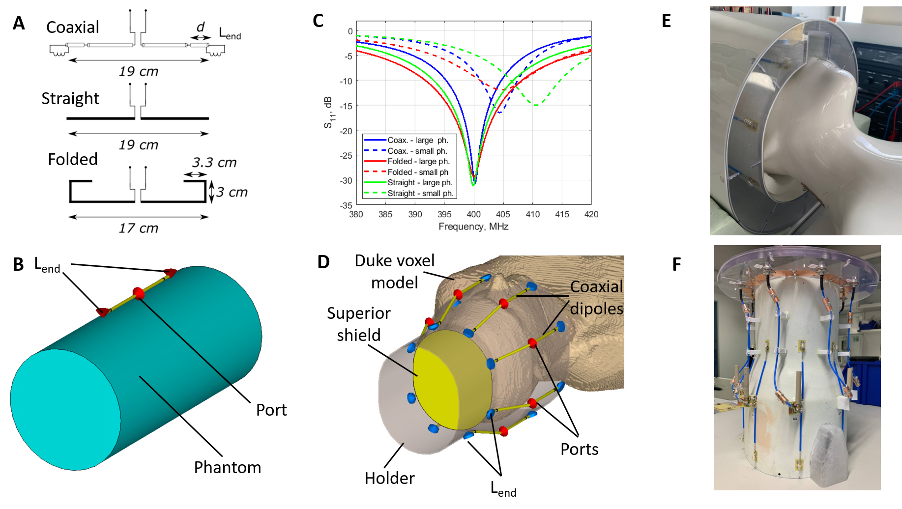
The developed array consisted of eight coaxial dipoles uniformly surrounding the head. Following work (6), the shield of each coaxial dipole had two gaps at small distances from both ends and inductors connecting the core and the shield (Fig.1A). We also modified the original geometry of coaxial dipoles (6) by shorting the inner and outer conductors at the feeding point (Fig .A). Distances 2 cm and 3 cm from the end to the gap were considered in this work. Smaller distances required very large inductances, while larger distances did not cause significant extension of the current distribution. The total length of the coaxial dipole was 19 cm. For comparison, we also evaluated a folded-end dipole, straight dipole, and straight dipole with lumped inductors placed near the ends (Figs.1A and 1B). For all dipoles, we assess the frequency variations using two setups consisting of single dipole elements and cylindrical phantoms (Fig.1B) (ε=58.6, σ=0.64 S/m, 17.6 and 14.2 cm in diameter) mimicking small and large heads. Frequency shifts measured for the coaxial and folded-end dipoles were similar and about two times smaller than that obtained for the straight dipole (Fig.1C). We also evaluated and compared current distributions along the dipole’s conductors and SAR-efficiencies (<B1+>/√pSAR, where pSAR is a local peak SAR). <B1+> was averaged over 13-cm transversal slab, which includes the majority of the brain. Based on these results, we chose the optimal coaxial dipole design with the gap position of 2 cm and inductance of 40 nH. Figs 1D-1F show the simulation model and photos of the final 8-element coaxial dipole array design. The array performance was compared to that of the previously developed eight-element folded-end dipole array of the similar size. B1+ and pSAR for both arrays driven in the CP-mode (Fig.1D) were simulated numerically using a head and shoulder (HS) phantom (Fig.1E) mimicking the human tissue property and the Duke voxel model. All numerical simulations were done using CST Studio 2021 (Dassault Systèmes, Vélizy-Villacoublay, France). All data were acquired using Siemens Magnetom 9.4T full body scanner. In the experiment, B1+ was measured using a satTFL sequence (7) (TR=2.5ms, TE=0.73ms, GRAPPA 2x2, FA=2˚/70˚, matrix: 64x64x64, resolution 3.5mm isotropic) for the HS phantom and healthy volunteer. In-vivo T1-weighted and T2*-weighted images of a healthy volunteer were acquired using MPRAGE (TI=1340ms, TR=3360ms, GRAPPA 2, matrix 264x264x224mm, resolution 0.8mm isotropic) and GRE (TR=11ms, TE=7ms, GRAPPA 2, FA=5˚, matrix 264x264x224mm, resolution 0.8mm isotropic).Results and Discussion
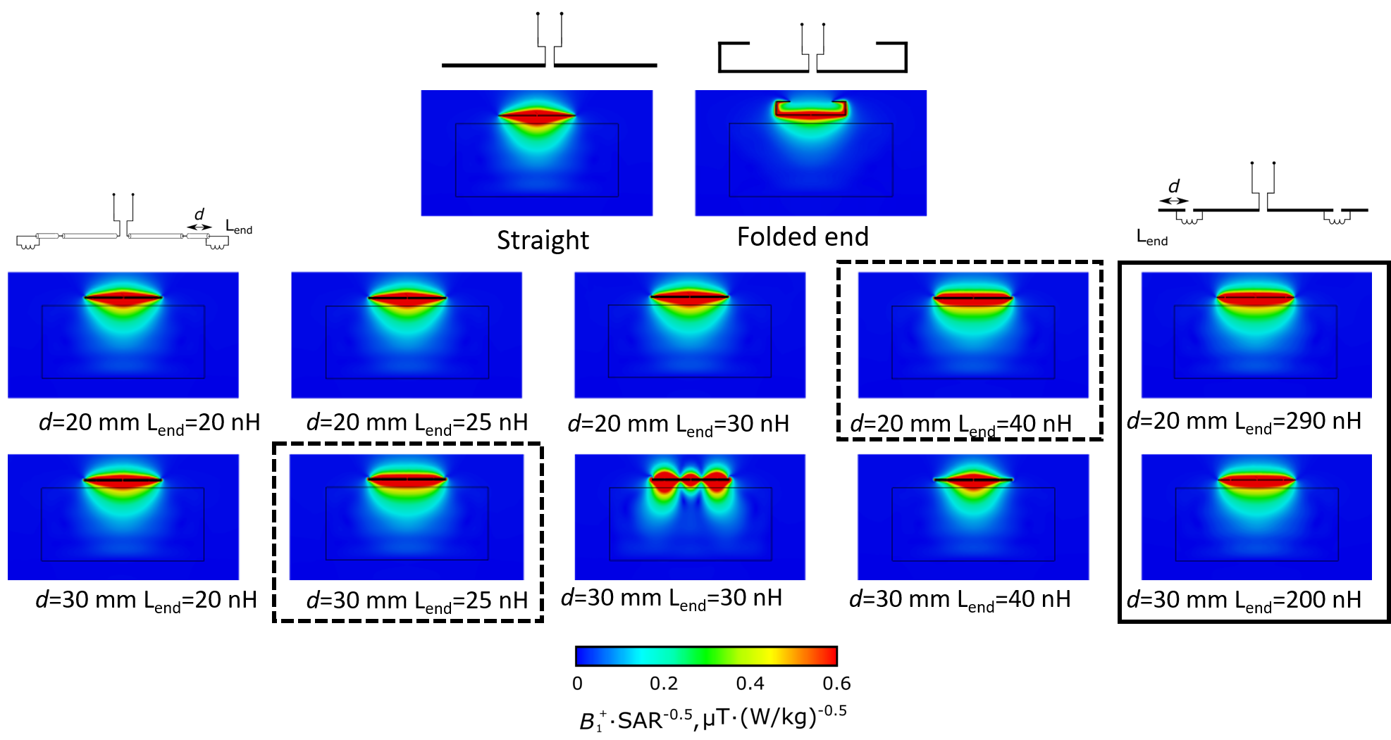
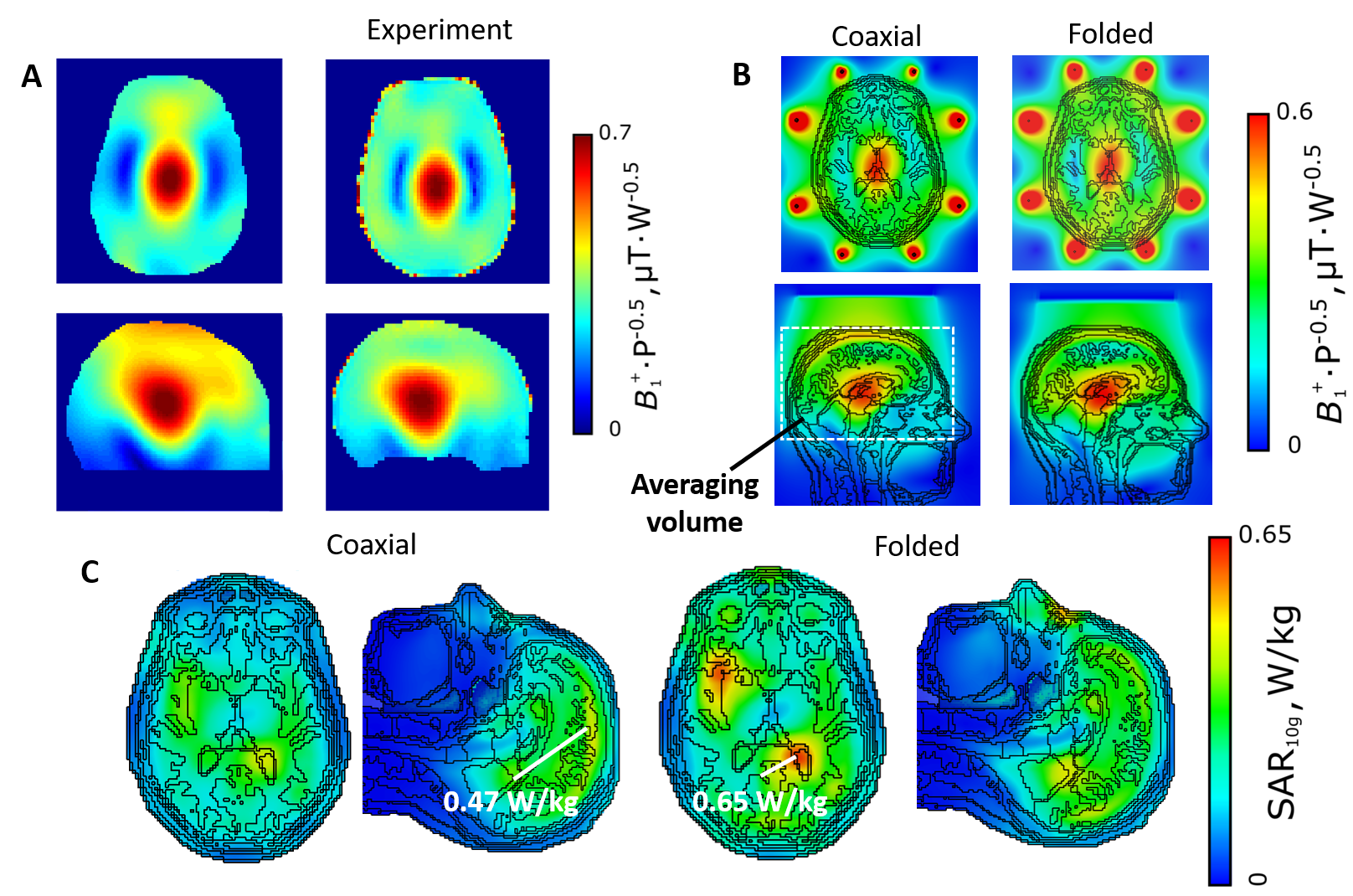
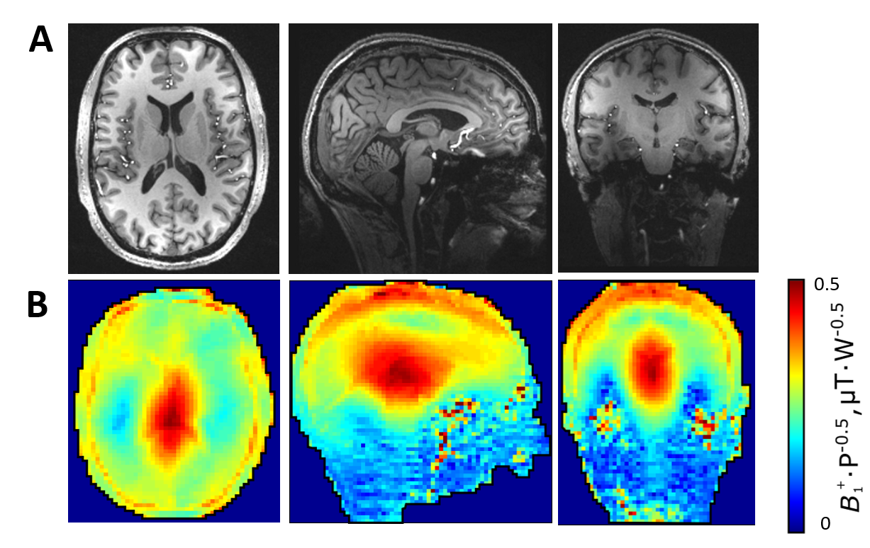
Figs.2 and 3 show SAR-efficiencies and corresponding current distributions for the single coaxial, folded-end, and straight dipoles all loaded by the cylindrical phantom (Fig.1B). While the current distribution of the straight dipole has an almost triangular shape, using coaxial dipole or straight dipole with lumped inductors allow flattening the current distribution and reducing SAR. As seen in Fig.2, straight dipoles with inductances at the ends also provide an extended current distribution, but the required inductance is much higher (290 vs 40nH). Smaller inductances allow for a decrease in coil losses. 8-element coaxial dipole array loaded by the Duke voxel model provides <B1+> of 0.395 µT/√W. In contrast, folded-end dipoles provide 0.427 µT/√W. However, the coaxial dipole design delivers 30% lower local pSAR value. As a result, SAR-efficiency for the coaxial dipole array is 10% higher than that for the folded dipole array. From the in-vivo measurements (Fig 5A) coaxial dipole array can provide whole-brain coverage. Thus, our numerical and experimental results show that the coaxial dipole array imaging performance is very similar to the folded dipole array.Conclusion
We developed, constructed, and evaluated the eight-element coaxial dipole array for human whole-brain imaging at 9.4T. The developed array provides a more compact and convenient alternative to the folded-end dipole design with an additional benefit of 10% higher SAR efficiencyAcknowledgements
Financial support of the ERC Advanced Grant “SpreadMRI”, No 834940 is gratefully acknowledged.References
1. Chen, Gang, et al. “A 7T 8 channel transmit-receive dipole array for head imaging: dipole element and coil evaluation.” Proceedings of the 22nd Annual Meeting of ISMRM, Milan, Italy. Vol. 621. 2014.
2. Clément, J., Gruetter, R., & Ipek, Ö. (2019). A combined 32‐channel receive‐loops/8‐channel transmit‐dipoles coil array for whole‐brain MR imaging at 7T. Magnetic resonance in medicine, 82(3), 1229-1241.
3. Avdievich, Nikolai I., et al. “Unshielded bent folded‐end dipole 9.4 T human head transceiver array decoupled using modified passive dipoles.” Magnetic resonance in medicine 86.1 (2021): 581-597.
4.Avdievich, Nikolai I., et al. “Evaluation of short folded dipole antennas as receive elements of ultra‐high‐field human head array.” Magnetic resonance in medicine 82.2 (2019): 811-824.
5.Avdievich, Nikolai I., et al. “Folded‐end dipole transceiver array for human whole‐brain imaging at 7 T.” NMR in Biomedicine 34.8 (2021): e4541. van Leeuwen, Carel C., et al. “The Coax Dipole: A fully flexible coaxial cable dipole antenna with flattened current distribution for body imaging at 7 Tesla.” Magnetic Resonance in Medicine 87.1 (2022): 528-540. Paper about the B1 mapping method
Figures
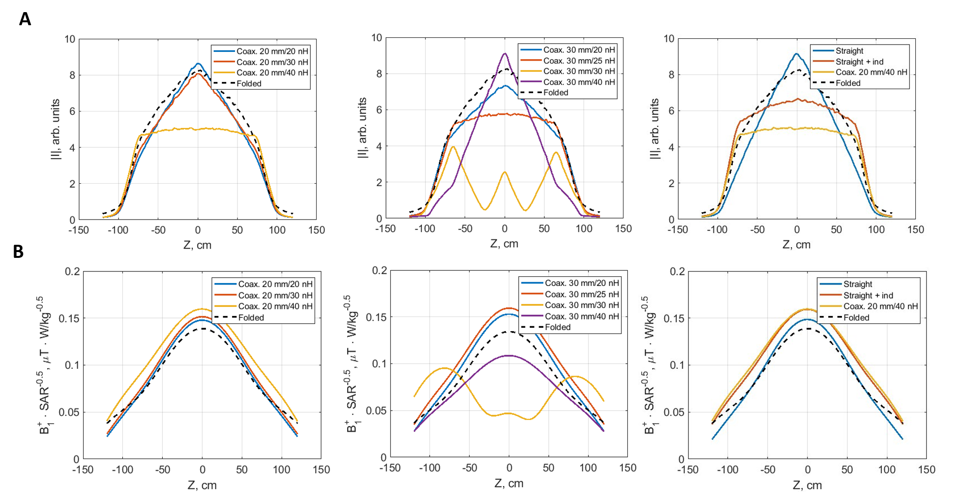
Current distribution along the dipole element conductors (A), SAR-efficiency in the center of the phantom for single dipole elements (B).