1059
128-channel brain imaging array with improved acceleration at 10.5 Tesla1Center for Magnetic Resonance Research, University of Minnesota, Minneapolis, MN, United States
Synopsis
Keywords: RF Arrays & Systems, RF Arrays & Systems
Described is a 128-channel receive (Rx) array for 10.5T brain imaging, comprised of 120 small Rx loops and 8 of the 16 transmitter elements used as receivers. The coil is compared to another 10.5T 64-Rx array and to 7T 32- and 64-Rx arrays. The principal benefit for the same field strength was improved parallel imaging. Secondarily, important engineering innovations are demonstrated to suppress transmit/receive interactions and optimize transmit efficiency. Modest improvements to peripheral SNR were achieved for the 10.5T 128-Rx over 64-Rx array. A 50% improvement in central SNR was realized with the use of transmitter elements as receivers.Introduction
Motivated by the advantages of ultrahigh-field, high-channel count arrays described previously [1] and demonstrated for head coils at 3T [2], 7T [3-7] and 10.5T [8,9], our group undertook construction of a 128-channel receive (Rx) array and reported preliminary results [10]. Herein we conclude by reporting results for a 128-channel Rx array which uses a 120-Rx array made up of small loops, and uses 8 of the 16-channel self-decoupled (SD) transmitter elements as transceivers (Tx/Rx) [11]. This 128-channel coil is compared to a 10.5T 64-Rx coil which also uses the same 16-channel SD loop transmit structure but without the use of transmit elements as receivers.Methods
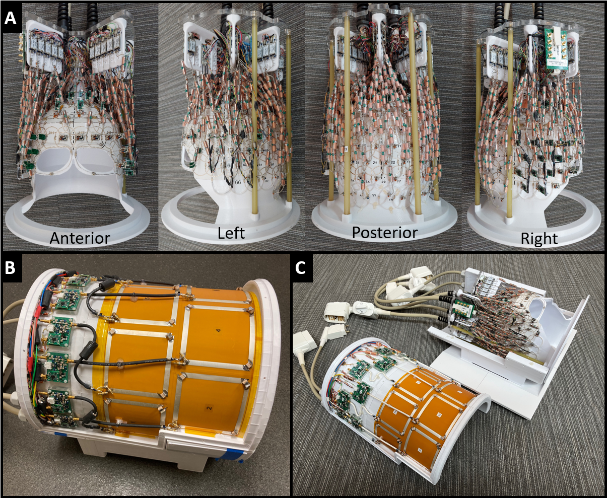
Coil construction was described in detail previously [10]. Originally intended as a 128-channel receive-only array, the number of small Rx loops were reduced to 120 to permit the use of 8 of the transmitter elements as receivers to make up the 128 Rx channels. The anterior eight loops of this transmitter array were used as transceivers to cover the hole left in the receiver former that accommodates the face. The advantages of larger transceiver loops to boost central SNR has been previously documented [12-15].The receive array loops were constructed of a hybrid of conductors. The majority were constructed of 1mm wide, 35 μm thick PCB traces on flexible laminates while a minority employed 18 AWG silver-plated copper wire. There are 59 on-coil and 61 off-coil preamps, with 8 T/R switches for the transceivers. Standard geometric (overlap) nearest-neighbor decoupling is employed throughout the receiver only array. The low-noise low input impedance preamp (WMA447D, WanTcom, Minneapolis, MN, USA) was used with standard preamp decoupling techniques [16], either using a series inductor for impedance transformation (on-coil) or quarter wavelength transformation (off-coil). Pi-network phase shifters were used whenever necessary to adjust the total cable phase. All conductors on the receive array which were within the transmit array (including DC cabling and coaxial cables) were segmented with RF chokes or cable traps [17], respectively, every 4-5 cm (~λ/16) to mitigate the effect of the receive array on the transmit B-field. In high field coil design, especially at 10.5T, every conductor must be treated like a potential antenna or radiator and must be segmented adequately to prevent self-resonance.
Experimental data was acquired on the Siemens MAGNETOM 10.5T system using a phantom mimicking electrical properties of the brain. B1+ maps were produced from an AFI sequence [18]. For consistency, unaccelerated SNR maps and 1/g maps were acquired and processed identical to previous work [3].
Results
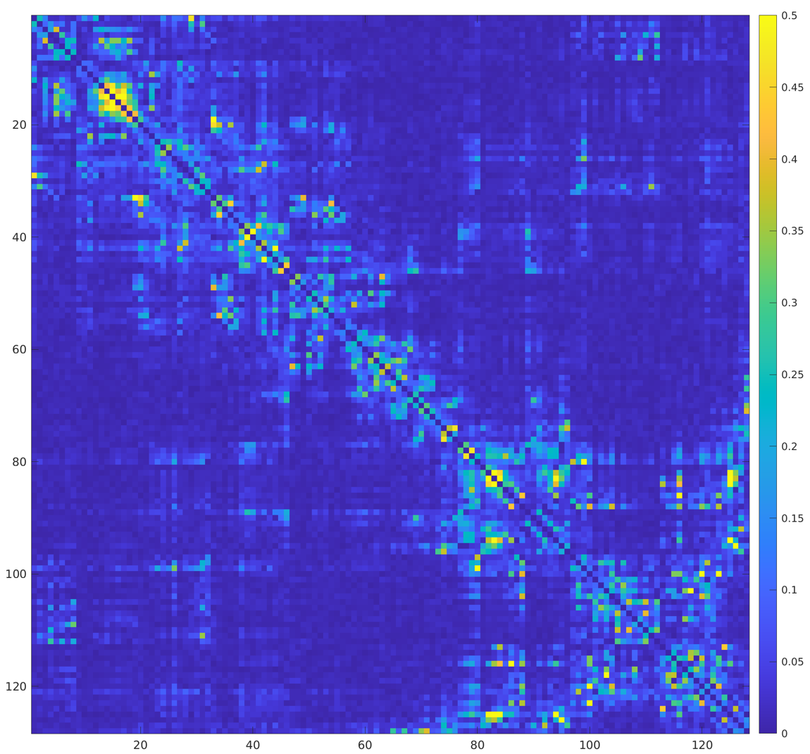
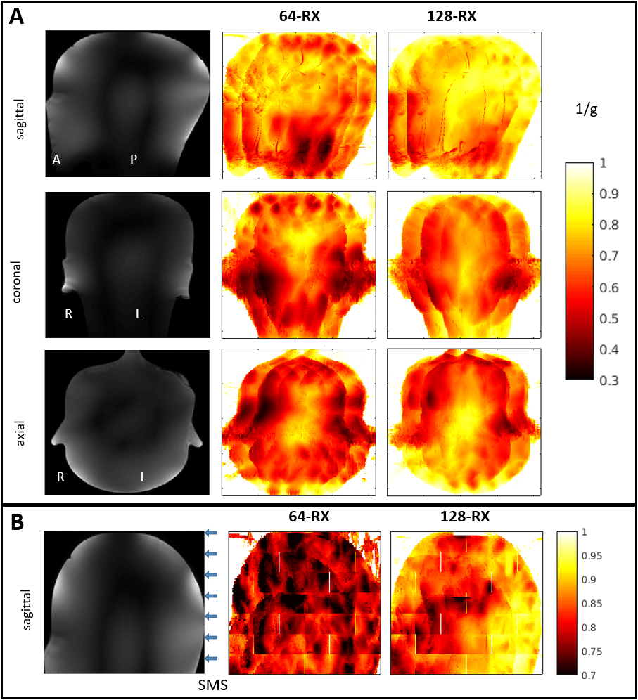
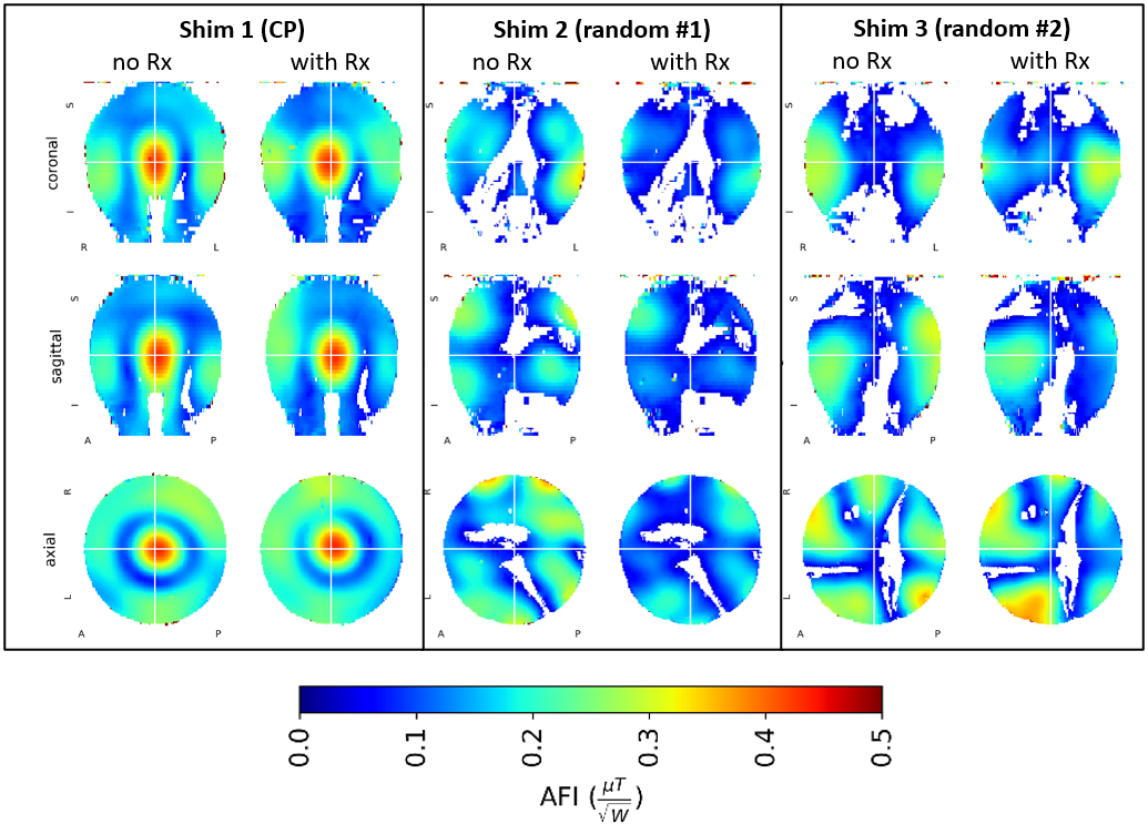
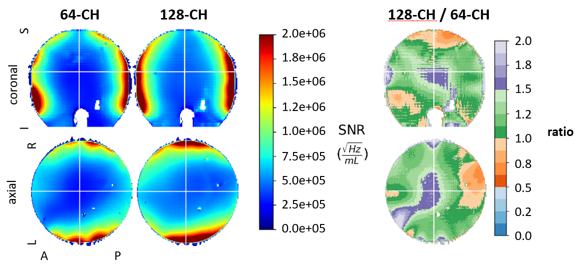
Presented are the noise correlation matrix for all 128 channels (figure 2), the 1/g MIP maps for R=8 (1D) (figure 3A) and MBxR = 7x2 comparing 64-channel and 128-channel arrays (figure 3B), B1+ maps without and with the 120-Rx array for three distinct B1+ shims (figure 4), and lastly SNR maps for the 64-Rx and 128-Rx arrays (figure 5).Discussion
The construction of the 128-channel array made significant departures from its 64-channel predecessor. From the decision to use on-coil preamps to the flex PCB loop conductors to the method of nearest-neighbor decoupling to the hundreds of cable traps on the feed cables, it is a distinctly different approach to the previous array.As we would expect from a higher channel count coil, we achieve better acceleration for the 128-channel over 64-channel coil (Figure 3). This is expected as long as noise correlation is reasonable. The mean/maximal 1/g achieved by the 128-channel coil for MBxR=7x2 is 0.91/0.81 vs 0.85/0.74 for the 64-channel. As a point of comparison, the 32-Rx (NOVA) and 64-Rx coils at 7T described in [3] had MBxR=7x2 mean/maximal 1/g of 0.65/0.41 and 0.81/0.58, respectively (though this was in human subjects instead of phantoms).
The receive array also achieves minimal interaction with transceiver array as demonstrated by the B1+ maps, lending credence to our approach of using regularly spaced cable traps throughout the array. While this added considerably to the complexity of the array and appears to completely screen the imaging sample from the transmitter, we preserved transmit efficiency and minimized modification of the transmit field as a result of introducing the receive array. This simplifies our EM simulations and safety validation process necessary to add our RF coils to the investigational device exemption (IDE) through the U.S. FDA which will allow for human imaging.
Gains to peripheral SNR expected with a greater channel count array were modest and unevenly distributed, perhaps due to compromises made in construction of this receive array, including for example, the use of PCB loop conductors which reduce Q-factor. Improvements to central SNR (up to 50%) are still realized largely as a result of the use of 8 loops from the transmitter for receive.
Conclusions
This work makes important contributions to the study of high-field, high-channel-count arrays. Improved parallel imaging performance with reduced EM interaction with the transmitter are demonstrate. While there is significant room for optimization to achieve greater peripheral SNR, this receive array is an important contribution in the sparse field of ultrahigh-field high-channel-count arrays. Important lessons have been learned regarding transmit/receive array interaction and we’ve successfully employed several mitigation strategies that will benefit high-field coil construction for years to come.Acknowledgements
This research was funded by NIH U01 EB025144, BTRC P41 EB027061, P30 NS076408, NIH S10 RR029672 grants.
Thanks to our interns Erne Habegger Mc Cabe and Marybelle Kim who assisted in circuit assembly.
References
[1] Wiesinger, F., Van de Moortele, P. F., Adriany, G., De Zanche, N., Ugurbil, K. & Pruessmann, K. P., 2006. Potential and feasibility of parallel MRI at high field. NMR Biomed 19, 368-378. Epub Date: 2006/05/18 PMID: 16705638
[2] Wiggins, G. C., Polimeni, J. R., Potthast, A., Schmitt, M., Alagappan, V. & Wald, L. L. 96-Channel receive-only head coil for 3 Tesla: design optimization and evaluation. (2009) Magn Reson Med 62, 754-762.
[3] Uğurbil, K., Auerbach, E., Moeller, S., Grant, A., Wu, X., Van de Moortele, P. F., Olman, C., DelaBarre, L., Schillak, S., Radder, J., Lagore, R. & Adriany, G., 2019. Brain imaging with improved acceleration and SNR at 7 Tesla obtained with 64-channel receive array. Magn Reson Med 82, 495-509. Epub Date: 2019/02/26 PMID: 30803023 PMCID: PMC6491243
[4] Mareyam, A., Kirsch, J.E., Chang, Y., Madan, G., Wald, L.L., 2020. A 64-Channel 7T array coil for accelerated brain MRI. ISMRM 2020, 0764.
[5] Gruber B, Stockmann JP, Mareyam A, Keil B, Ghotra A, Feinberg DA, Wald LL. A 128-Channel head coil array for Cortical Imaging at 7 Tesla. ISMRM 2021, 0176. Available online: https://cds.ismrm.org/protected/21MProceedings/PDFfiles/0176.html
[6] Gunamony S, Müller R, McElhinney P, Williams SN, Groß-Weege N, Weiskopf N, Möller HE, Feinberg D. A 16-channel transmit 96-channel receive head coil for NexGen 7T scanner. ISMRM 2021, 0182. Available online: https://cds.ismrm.org/protected/21MProceedings/PDFfiles/0182.html
[7] Hendriks, A. D., Luijten, P. R., Klomp, D. W. J. & Petridou, N. Potential acceleration performance of a 256-channel whole-brain receive array at 7 T. (2019) Magn Reson Med 81, 1659-1670.
[8] Tavaf N, Lagore RL, Jungst S, Gunamony S, Radder J, Grant A, Moeller S, Auerbach E, Ugurbil K, Adriany G, Van de Moortele P-F. A self-decoupled 32-channel receive array for human-brain MRI at 10.5 T. Magn Reson Med. 2021; 86: 1759– 1772. https://doi.org/10.1002/mrm.28788
[9] Tavaf N, Jungst S, Lagore RL, Radder J, Moeller S, Grant A, Auerbach E, Ugurbil K, Adriany G, Van de Moortele P-F. A Self-decoupled 64 Channel Receive Array for Human Brain MRI at 10.5T. ISMRM 2021, 0179. Available online: https://cds.ismrm.org/protected/21MProceedings/PDFfiles/0179.html
[10] Lagore RL, Jungst S, Radder J, Auerbach EJ, Moeller S, Grant A, DelaBarre L, Waks M, Van de Moortele P-F, Adriany G, Ugurbil K. A 128-channel receive array for 10.5T human head imaging. ISMRM 2021, 0177. Available online: https://cds.ismrm.org/protected/21MProceedings/PDFfiles/0177.html
[11] Waks M, Tavaf N, Lagore R, Jungst S, Radder J, Grant A, DelaBarre L, Van de Moortele P-F, Adriany G, Ugurbil K. A 16-channel splittable non-overlapped self-decoupled loop transmitter for 10.5 Tesla human head imaging. ISMRM 2022, 4109. Available online: https://cds.ismrm.org/protected/22MProceedings/PDFfiles/4109.html
[12] Adriany, G., Auerbach, E.J., Snyder, C.J., Gözübüyük, A., Moeller, S., Ritter, J., Van de Moortele, P.-F., Vaughan, T. and Uğurbil, K. (2010), A 32-channel lattice transmission line array for parallel transmit and receive MRI at 7 tesla. Magn. Reson. Med., 63: 1478-1485. https://doi.org/10.1002/mrm.22413
[13] Avdievich, N. I., Giapitzakis, I. A., Bause, J., Shajan, G., Scheffler, K. & Henning, A. Double-row 18-loop transceive-32-loop receive tight-fit array provides for whole-brain coverage, high transmit performance, and SNR improvement near the brain center at 9.4T. (2019) Magn Reson Med 81, 3392-3405.
[14] Gosselink, M, Hoogduin, H, Froeling, M, Klomp, DWJ. No need to detune transmitters in 32-channel receiver arrays at 7 T. NMR in Biomedicine. 2021; 34:e4491. https://doi.org/10.1002/nbm.4491
[15] Lagore RL, Moeller S, Zimmermann J, DelaBarre L, Radder J, Grant A, Ugurbil K, Yacoub E, Harel N, Adriany G. An 8-dipole transceive and 24-loop receive array for non-human primate head imaging at 10.5 T. NMR in Biomedicine. 2021; 34:e4472. https://doi.org/10.1002/nbm.4472
[16] Roemer PB, Edelstein WA, Hayes CE, Souza SP, Mueller OM. The NMR Phased Array. Magn Reson Med. 1990, 16: 192-225. https://doi.org/10.1002/mrm.1910160203
[17] Seeber D, Jevtic J, Menon A. Floating Radio Frequency Balun for Suppression of Shield Currents. ISMRM 2003, 2377. Available online: https://cds.ismrm.org/ismrm-2003/2377.pdf
[18] Yarnykh, VL. Actual flip-angle imaging in the pulsed steady state: A method for rapid three-dimensional mapping of the transmitted radiofrequency field. Magn. Reson. Med. 2007, 57: 192-200. https://doi.org/10.1002/mrm.21120
Figures