1058
Evaluation of Coupling between A 32-channel Sleeve Antenna Receiver Array to A 16-channel Loop Transmitter for The Human Head Imaging at 10.5 T1University of Ulsan, Ulsan, Korea, Republic of, 2Center for Magnetic Resonance Research, Minneapolis, MN, United States
Synopsis
Keywords: RF Arrays & Systems, RF Arrays & Systems
We evaluated in simulation and experimentally the effects that the insertion of a 32-channel sleeve antenna receiver array has on the B1+ and SAR performance of a 447 MHz/10.5 T 16-channel loop transmitter array. For this we carefully developed accurate models of both the 16-channel loop transmitter and the 32-channel sleeve antenna receiver, compared simulated with experimental B1+ and evaluated the expected SAR efficiency of the 16-channel loop transmitter array with and without the 32-channel sleeve antenna receiver array insert.Introduction
High channel count radiative antenna (e.g. dipole) head arrays for increased sensitivity have been proposed and reported at ultra-high field (UHF)[1-5]. However, dipole antennas and their coaxial feed cables (typically routed in parallel with one leg of the dipole antenna) can cause detrimental interactions in practice, particularly for head applications. This is further exaggerated in arrays at UHF as the wavelengths of the applicable RF signals at 10.5T, become shorter, where even short coaxial cables associated with a receive coil feed point approach l/4 length and significantly interact with a transmit coil[6]. The resulting interaction between a transmit coil, a receive coil, and coaxial cables can generate complex field interference which cannot be easily resolved. Naturally, radiative antenna arrays present greater challenges in minimizing the mutual coupling between neighboring elements, and consequently, more robust decoupling approaches need to be developed for high channel count arrays. In our previous publication[7], we introduced a sleeve antenna concept for a transceiver array where we demonstrated improved element decoupling and cable interference without losing antenna efficiency. Similarly a sleeve antenna receiver array has the potential to reduce the coaxial cable related interference[8,9]. Previously, we developed, built and presented[10] a high density azimuthal 32-channel sleeve antenna receiver array with shunt PIN diode detuning. Contrary to expectation, this receiver array interacted only modestly with the transmitter and showed substantial higher peripheral signal to noise ratio (SNR). For the safety validation of the interaction of the 32-channel sleeve antenna receiver array with the 16-channel loop transmitter array, we carefully evaluate the transmitter array in terms of the B1+ efficiency, 10 g specific absorption rate (SAR), and SAR efficiency and characterize this without and with the receiver array.Methods
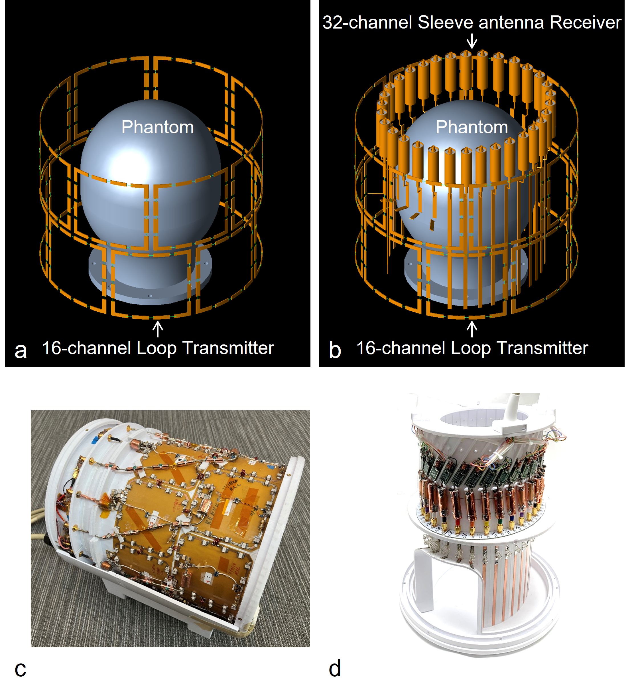
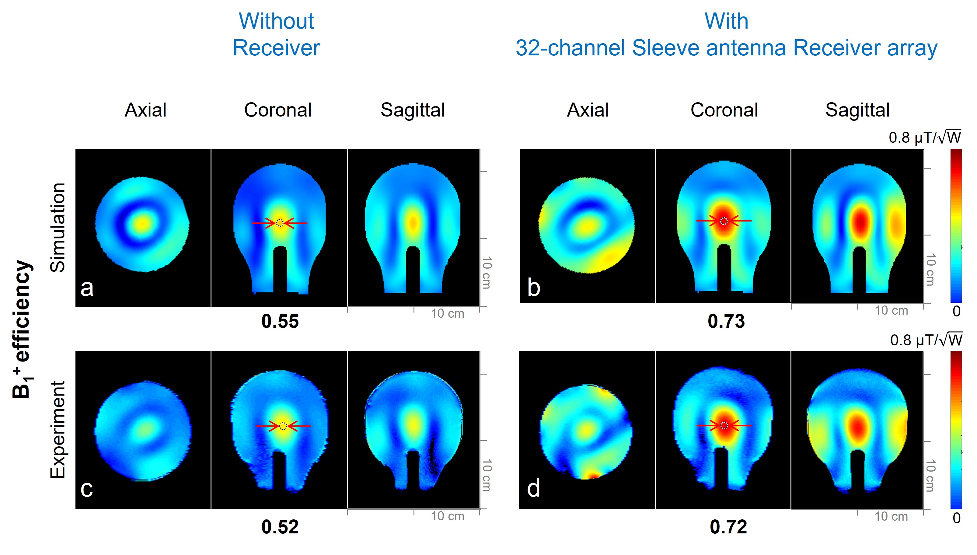
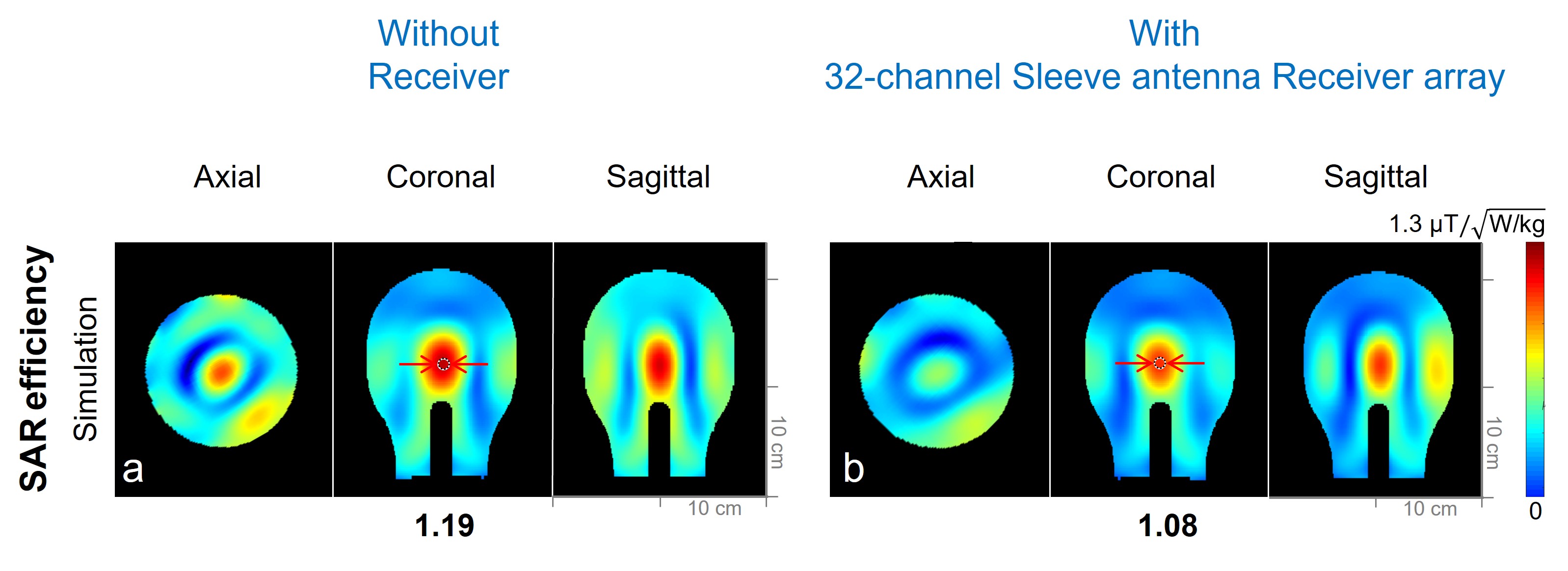
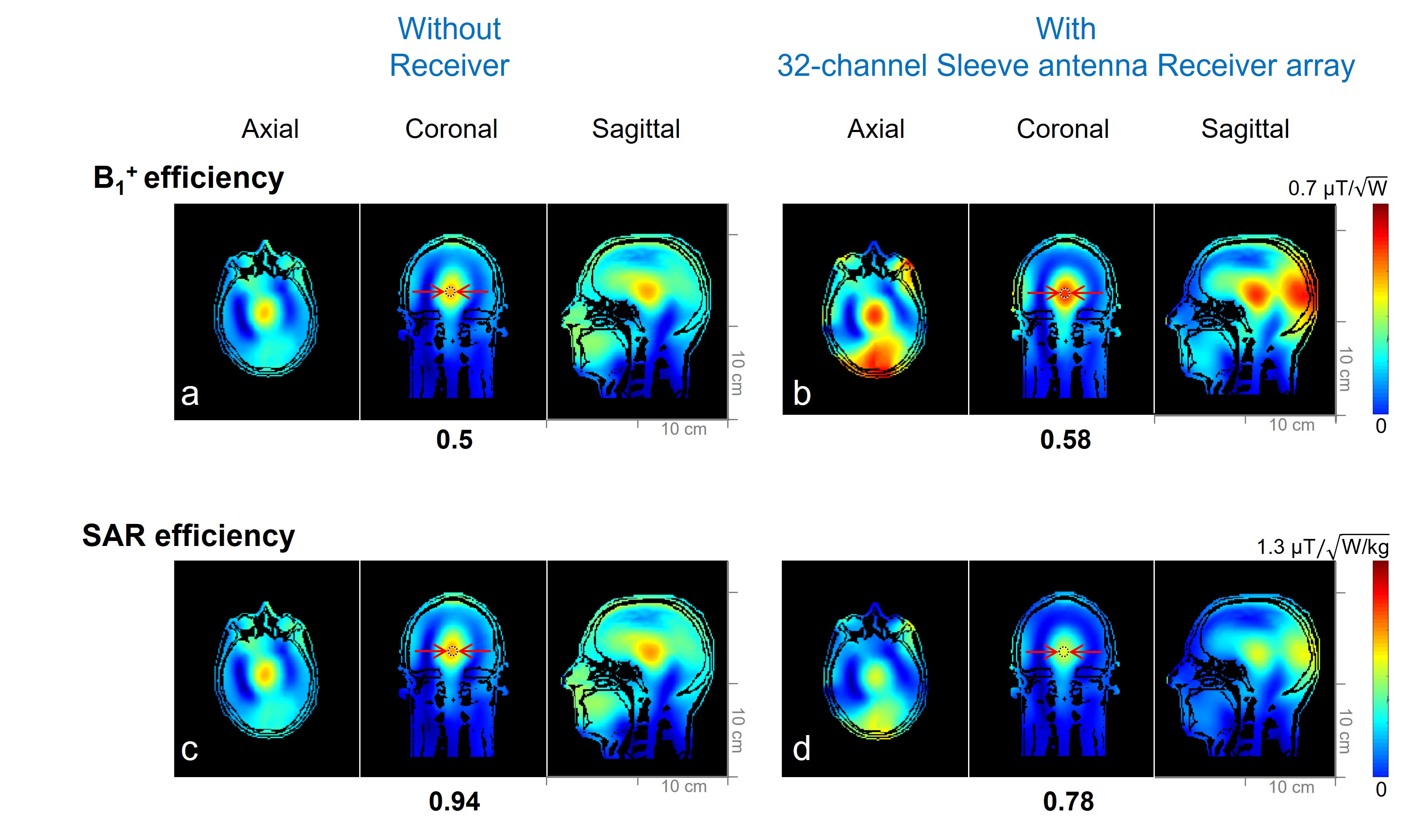
Accurate 3D CAD renderings of the 16-channel loop transmitter array without (Fig. 1a) and with (Fig. 1b) the 32-channel sleeve antenna receiver array are shown along the physically built 16-channel loop transmitter (Fig. 1c) and the 32-channel sleeve antenna receiver (Fig. 1d) arrays. The transmitter array consisted of sixteen 10 × 10 cm2 loop coils arranged in two rows of eight channels. The 3D printed conformal former supported the inner receiver (the 32-channel sleeve antenna array) insert. Each loop of the transmitter was built with 15 distributed capacitors (ATC, Huffington Station, NY) and used inductive decoupling between the nearest neighbors. The transmitter was detuned using PIN diodes (MACOM, Lowell, MA) signal reception. During the transmit phase, this loop transmitter was fully tuned and resonant at 447MHz. The reciever array dimensions are: 19 cm × 22.6 cm with azimuthally arranged 32 individual elements tightly spaced at 1.5 cm apart. Floating cable traps were used for each sleeve antenna element 8,9. Simulated B1+ efficiency was calculated using XFdtd (REMCOM, State College, PA) as shown in Fig. 2a and 2b. With a 10.5 T MR Siemens console, experimental B1+ fields were obtained using an actual flip angle imaging (AFI) sequence11 for a cylindrical phantom (17 cm diameter and 30.5 cm long) with uniform electrical properties (σ = 0.6 S/m and εr = 49) in Fig. 2c and 2d. B1+ fields were normalized to 1 W for B1+ efficiency (µT/√W) using MATLAB (Mathworks, Inc., Natick, MA, USA). For the safety validation, 10 g SAR and SAR efficiency (Fig, 3) was calculated. Finally, we compared the performance of the transmitter array without and with the receiver array with a human model (Duke) as shown in Fig. 4.Results
As shown in Fig. 2, a notable improvement (24.7%) of the B1+ efficiency with the 32-channel sleeve antenna receiver array was observed both in the simulation and the experiment compared to without the receiver array. However, the associated SAR efficiency with the receiver array inserted is 10.2% lower compared to just the transmitter alone as shown in Fig. 3. As shown in Fig. 4, 16% lower B1+ efficiency (Fig. 4a and 4b) and 17% higher SAR efficiency (Fig. 4c and 4d) without the 32-channel sleeve antenna receiver array is achieved compared to the B1+ efficiency with the receiver array.Discussion & Conclusion
We were able to build excellent models, accurately representing our transmitters and the sleeve receiver array. We can observe notable interaction between the transmitter array with a 32-channel sleeve antenna receiver array even after active PIN diode aided decoupling – this effect is similar to previously reported work describing deliberate B1+ field manipulations through inductively coupled resonant[12,13] or conductive structures[14]. While bench measurements and experimental results indicate that the achievable detuning values with shunt PIN diodes are sufficient for reduced transmitter/receiver interaction, and preamplifier protection for the ~l/4 sleeve antenna conductors, interaction between the outer transmitter and the inner receiver remain. While it is possible to add additional PIN diodes to further disrupt the sleeve antenna’s conductive structure, the associated circuitry was found to introduce secondary coupling issues while not improving overall detuning values (~20dB) or preamplifier protection. Since we achieved good agreement between simulation and experimental validation, rather than add disruptive additional sleeve conductor detune circuitry, similar to recent work presented by Alipour[13] and Schmidt[14], we plan to use the B1+ enhancing remaining resonance characteristics of sleeve antenna elements to our advantage for improved transmit performance and SNR.Acknowledgements
NIH-U01-EB025144, NIH-S10-RR029672, NIH-BTRC-P41-EB027061 and NIH-P30-NS07640, "Leaders in INdustry-university Cooperation 3.0" Project, supported by the Ministry of Education and National Research Foundation of KoreaReferences
1. N. Avdievich et al., A 32‐element loop/dipole hybrid array for human head imaging at 7 T. Magn reson in Med 88, 1912-1926 (2022).
2. J. Clément et al., A human cerebral and cerebellar 8‐channel transceive RF dipole coil array at 7T. Magnetic resonance in medicine 81, 1447-1458 (2019).
3. A. Raaijmakers et al., The fractionated dipole antenna: A new antenna for body imaging at 7 T esla. Magn Reson Med 75, 1366-1374 (2016).
4. G. Wiggins et al., The electric dipole array: an attempt to match the ideal current pattern for central SNR at 7 Tesla. Proceedings of the 20th scientific meeting, International Society for Magnetic Resonance in Medicine, Melbourne, Australia 541 (2012).
5. M. Woo et al., A 16-Channel Dipole Antenna Array for Human Head Magnetic Resonance Imaging at 10.5 Tesla. Sensors 21, 7250 (2021).
6. R. Lagore et al., in Proc Intl Soc Mag Reson Med 29. 177.
7. M. Woo et al., Comparison of 16-channel asymmetric sleeve antenna and dipole antenna transceiver arrays at 10.5 Tesla MRI. IEEE Trans Med Imaging 40, 1147 - 1156 (2020).
8. D. Seeber et al., Floating shield current suppression trap. Concept Magn Reson B 21b, 26-31 (2004).
9. M. Woo et al., Evaluation of 8-Channel Radiative Antenna Arrays for Human Head Imaging at 10.5 Tesla. Sensors 21, 6000 (2021).
10. M. Woo et al., in Proc Intl Soc Mag Reson Med 29. 236.
11. V. Yarnykh, Actual flip-angle imaging in the pulsed steady state: a method for rapid three-dimensional mapping of the transmitted radiofrequency field. Magn Reson Med 57, 192-200 (2007).
12. S. Wang et al., B1 homogenization in MRI by multilayer coupled coils. IEEE Trans Med Imaging 28, 551-554 (2009).
13. A. Alipour et al., Improvement of magnetic resonance imaging using a wireless radiofrequency resonator array. Sci Rep 11, 23034 (2021).
14. Schmidt, R. & Webb, A. Metamaterial Combining Electric- and Magnetic-Dipole-Based Configurations for Unique Dual-Band Signal Enhancement in Ultrahigh-Field Magnetic Resonance Imaging. ACS Appl Mater Interfaces 9, 34618-34624 (2017).
Figures