1057
An Open 60-channel Tx/ 32-channel Rx RF Coil System for Routine Use at 7T
Andrea N Sajewski1, Tales Santini1, Anthony DeFranco1, Boris Keil2, Hecheng Jin1, Jacob Berardinelli1, Jinghang Li1, Cong Chu1, Tiago Martins1, and Tamer S Ibrahim1
1University of Pittsburgh, Pittsburgh, PA, United States, 2Institute of Medical Physics and Radiation Protection, TH Mittelhessen University of Applied Sciences, Giessen, Germany
1University of Pittsburgh, Pittsburgh, PA, United States, 2Institute of Medical Physics and Radiation Protection, TH Mittelhessen University of Applied Sciences, Giessen, Germany
Synopsis
Keywords: New Devices, Neuro
A 60-channel transmit array for 7T neuro MRI was implemented using the Tic-Tac-Toe coil design. The transmit coil and the receive insert are open in the front to promote patient comfort and reduce claustrophobia. By performing RF shimming on three head models, we optimized the coil for a range of ages and head sizes/shapes for use in sTx mode. Simulations, experimental B1+ maps and in-vivo images demonstrate consistency across subjects, showing extended coverage into the temporal lobe, cerebellum, brainstem and C5-C6 spinal cord segments. High quality images are currently being acquired using this coil in over 30 human studies.Introduction
The Tic-Tac-Toe (TTT) coil design1-4 has demonstrated the ability to provide homogeneous and load-insensitive B1+ for 7T MRI, a challenge at ultra-high field due to the reduced RF wavelength. Our recently developed 60-channel transmit array shows improvements in homogeneity and efficiency with smaller sized TTT coil modules and more degrees of freedom in RF shimming5-7. To implement a single non-subject specific shim case that will provide homogeneous B1+ over a variety of head sizes, we optimized the coil over three anatomically detailed head models: adult male, adult female, and child female. The RF shim case with sufficient coverage and homogeneity was implemented in single-channel mode in a 7T scanner and has been used in over 400 in-vivo human scans to date as part of more than 30 human studies.Methods
The 60-channel TTT coil consists of a double-row octagonal array of 4.25in x 4.25in TTT modules, each with 4 transmit channels, as displayed in Figure 1. The frame and housing were 3D printed in ABS and polycarbonate, and the TTT struts were CNC machined from Rexolite; the struts and shield were wrapped in 17.5μm-thick copper. The coil was tuned and matched to 297.2 MHz using both copper rods inserted into the struts and fixed capacitors. Additional capacitors were used between the panels to connect the ground and reduce eddy currents. The 32-channel receive insert was 3D printed to fit within the transmit coil.Finite difference time domain (FDTD) simulations with transmission line and capacitor models were performed using in-house developed software on a spherical water phantom and the head models Duke (male, age 34, 155lbs), Ella (female, age 26, 126lbs), and Billie (female, age 11, 75lbs) from the IT’IS Foundation Virtual Family8, as shown in Figure 1. RF shimming was performed using MATLAB optimization methods (GlobalSearch) on the three head models simultaneously, using a whole-head ROI from the bottom of the cerebellum, excluding nasal cavities and ears. The objective function used was the coefficient of variation over minimum (CV/min) B1+.
Using Wilkinson power splitters based on Yan et al.9 and varying cable lengths for phase adjustment, a chosen optimal RF shim case was implemented so that the coil can be used in single-channel mode on a 7T MAGNETOM scanner (Siemens, Erlangen, Germany). Experimental B1+ maps were acquired using a Turbo-FLASH sequence with the following parameters: TR/TE = 2000/1.16ms; TA = 12 min; flip angle from 0° to 90° in 18° increments; 3.2mm isotropic resolution. T2-FLAIR images were acquired with the following parameters: TR/TE = 14s/99ms; TA = 12 min; 0.75mm x 0.75mm x 1.5mm. T2-TSE images were acquired with the following parameters: TR/TE = 10s/61ms; TA = 8 min; 0.375mm x 0.375mm x 1.5mm.
Results
As seen in Figure 2, simulations and benchtop measurements of a representative channel/panel show consistency of s-parameters regardless of load. Figure 3 shows the B1+ from the optimized RF shim case on the Duke, Ella, and Billie models. Average B1+ for each model is shown. Average SAR (W/kg) per 1W calculated over the whole head is 0.0462 in Duke, 0.0473 in Ella, and 0.0523 in Billie, with peak/average SAR of 3.12, 2.66, and 2.96 respectively. Losses due to the plug, cables, and splitters were measured to be 10%, and losses due to the receive coil, decoupling circuits, and transmit coil structure are estimated to be 15%. All the losses are considered in the abovementioned values. Experimental B1+ maps show similar distributions and intensities to the simulations; Figure 4 shows 5 in vivo B1+ maps out of more than 20 acquired to date.Discussion and Conclusion
The 60-channel TTT Tx coil provides coverage throughout the brain and into the cerebellum and temporal lobes, brainstem, and up to C5-C6 which are typically regions of low B1+ at 7T. The tuning and matching of the coil are consistent across different heads, and optimizing over 3 head models of different size and position enables the coil to perform well for a range of ages and head types. In vivo B1+ maps show consistency across different subjects and match the FDTD simulations. Images obtained using this coil (Figure 5) demonstrate excellent SNR, homogeneity, and coverage. Furthermore, the open design of the coil promotes patient comfort and reduces claustrophobia.Acknowledgements
This work was supported by the National Institutes of Health under award numbers R01MH111265, R01AG063525, R56AG074467, and T32MH119168, and by the National Science Foundation Graduate Research Fellowship under Grant No. 1747452. This work was supported in part by the University of Pittsburgh Center for Research Computing through the resources provided.References
- Kim, J., et al. (2016). “Experimental and numerical analysis of B1+ field and SAR with a new transmit array design for 7T breast MRI.” J Magn Reson 269: 55-64.
- Krishnamurthy, N., et al. (2019). “Computational and experimental evaluation of the Tic-Tac-Toe RF coil for 7 Tesla MRI.” PLoS ONE 14(1): e0209663.
- Santini, T., et al. (2018). “In-vivo and numerical analysis of the eigenmodes produced by a multi-level Tic-Tac-Toe head transmit array for 7 Tesla MRI.” PLoS ONE 13(11): e0206127.
- Santini, T., et al. (2020). “Improved 7 Tesla Transmit Field Homogeneity with Reduced Electromagnetic Power Deposition Using Coupled Tic Tac Toe Antennas.” Sci Rep 11: 3370.
- Santini, T., et al. (2017). “64-channel Double-Octagon Tx Head Coil for 7T Imaging.” In Proc. of the 25th International Society of Magnetic Resonance in Medicine Annual Meeting, Honolulu, Hawaii, USA.
- Santini, T., et al. (2019). “Homogeneous 64-channel RF transmit array for brain imaging at 7T, 9.4T, and 10.5T.” In Proc. of the 27th International Society of Magnetic Resonance in Medicine Annual Meeting, Montreal, Quebec, Canada.
- Santini, T., et al. (2021). “A 28-channel decoupled Tic-Tac-Toe transmit radiofrequency coil for 7T MRI.” In Proc. Of the 2021 International Society of Magnetic Resonance in Medicine Annual Meeting.
- Christ, A., et al. (2009). “The Virtual Family – development of surface-based anatomical models of two adults and two children for dosimetric simulations.” Phys Med Biol 55: 23.
- Yan, X., et al. (2018). “Ratio-adjustable power splitters for array-compressed parallel transmission.” Magn Reason Med 79(4): 2422.
Figures
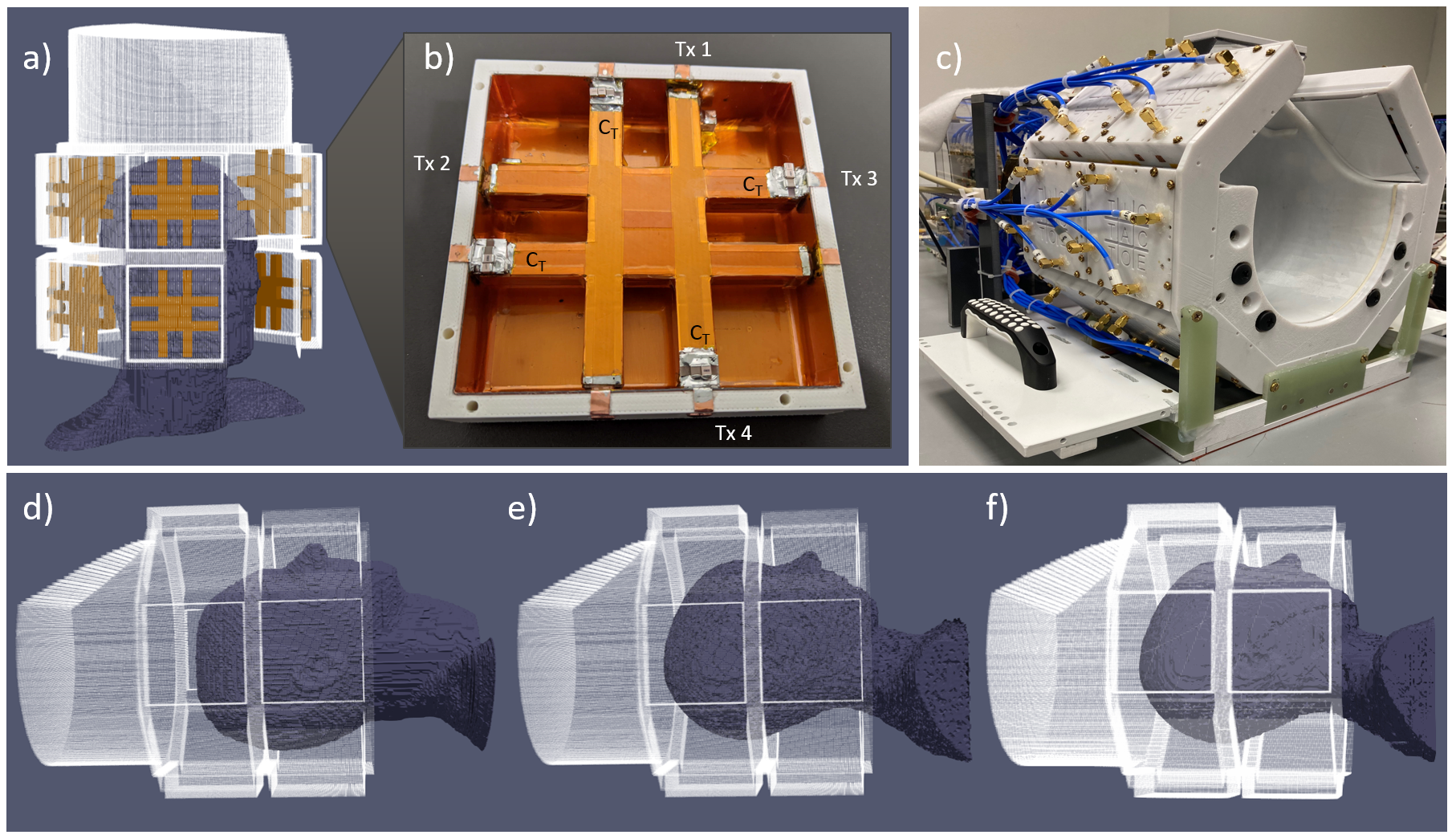
Figure 1: a) 3D model of 60-channel Tic-Tac-Toe (TTT) coil; b) single TTT panel, with mapping of transmission lines (Tx 1 – Tx 4), and tuning capacitors (CT); c) assembled 60-channel TTT coil with Rx insert; d-f) anatomically detailed head models Duke (34yo M/155lbs), Ella (26yo F/126lbs) and Billie (11yo F/75lbs) from IT’IS Virtual Family positioned in the coil.
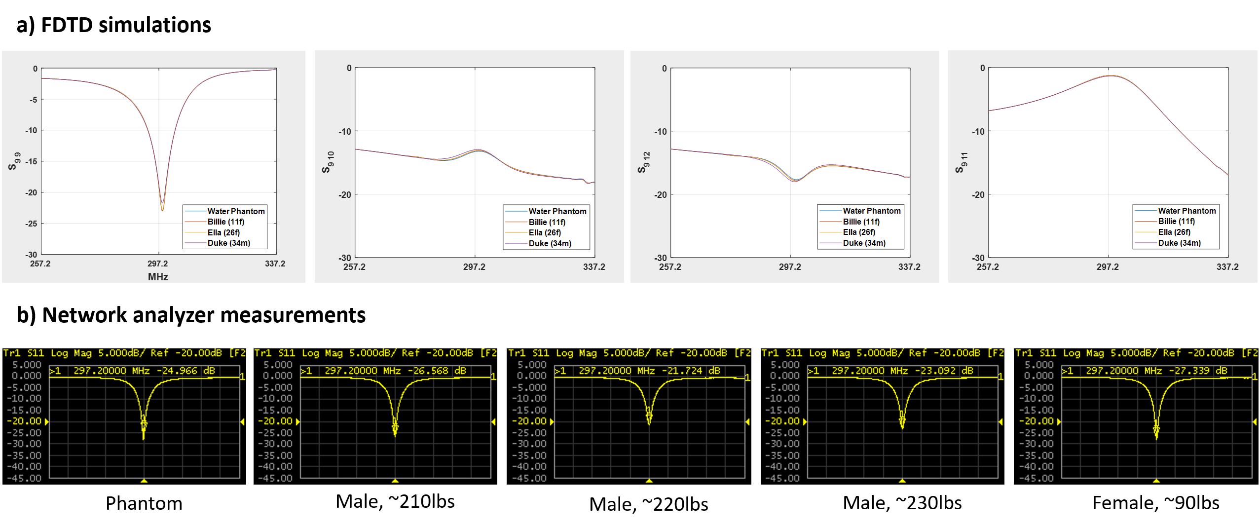
Figure 2: a) Simulated S11 of a representative channel and coupling between channels on a TTT panel with 4 different loads: water phantom and head models Duke (34yo M, 155lbs), Ella (26yo F, 126lbs), and Billie (11yo F, 75lbs). b) Experimental S11 of a representative channel with 5 different loads: a water phantom and 4 volunteers.
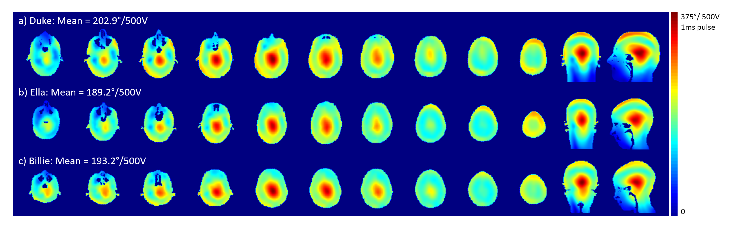
Figure 3: Simulated B1+ provided by the optimized non-subject specific RF shim case, on a) Duke (34yo M, 155lbs), b) Ella (26yo F, 126lbs), and c) Billie (11yo F, 75lbs) models from the Virtual Family, scaled from 0 to 375° per 500V for a 1ms pulse. Losses considered are 10% measured from the plug, cables, and splitters, and 15% estimated from the receive coil, decoupling circuits, and transmit coil structure. The first axial slice shown is just below the cerebellum on all models. Mean B1+ is displayed for each head model, calculated over the whole head from the bottom of the cerebellum.
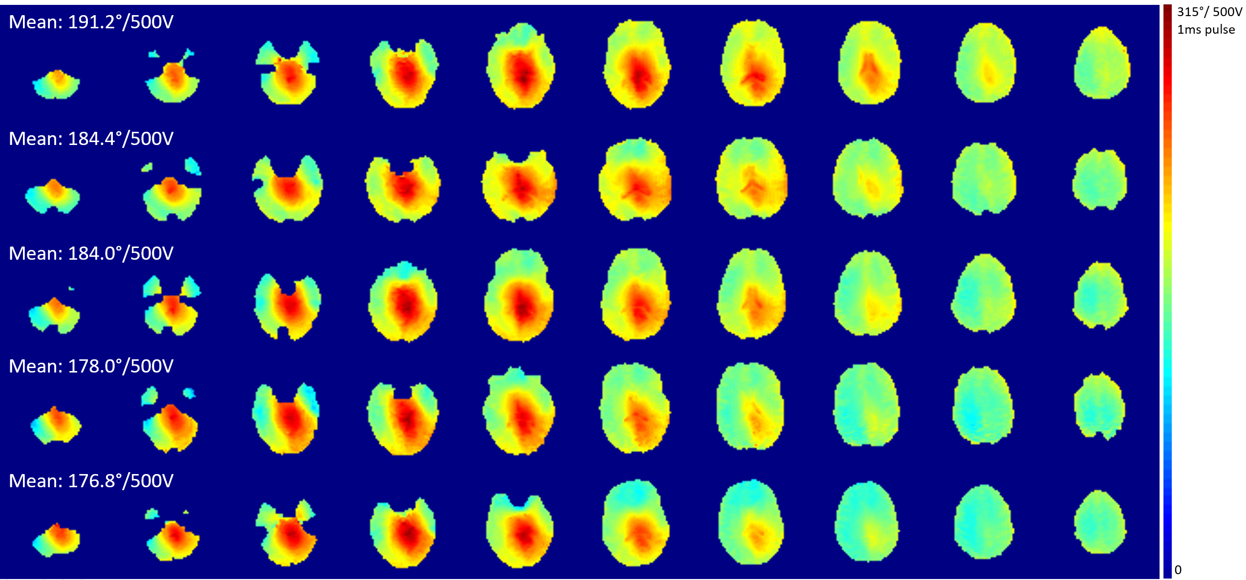
Figure 4: Experimental B1+ maps on 5 volunteers using the implemented non-subject specific RF shim case in sTx mode, scaled from 0 to 315° per 500V for a 1ms pulse. The mean B1+ calculated over the whole brain is shown.
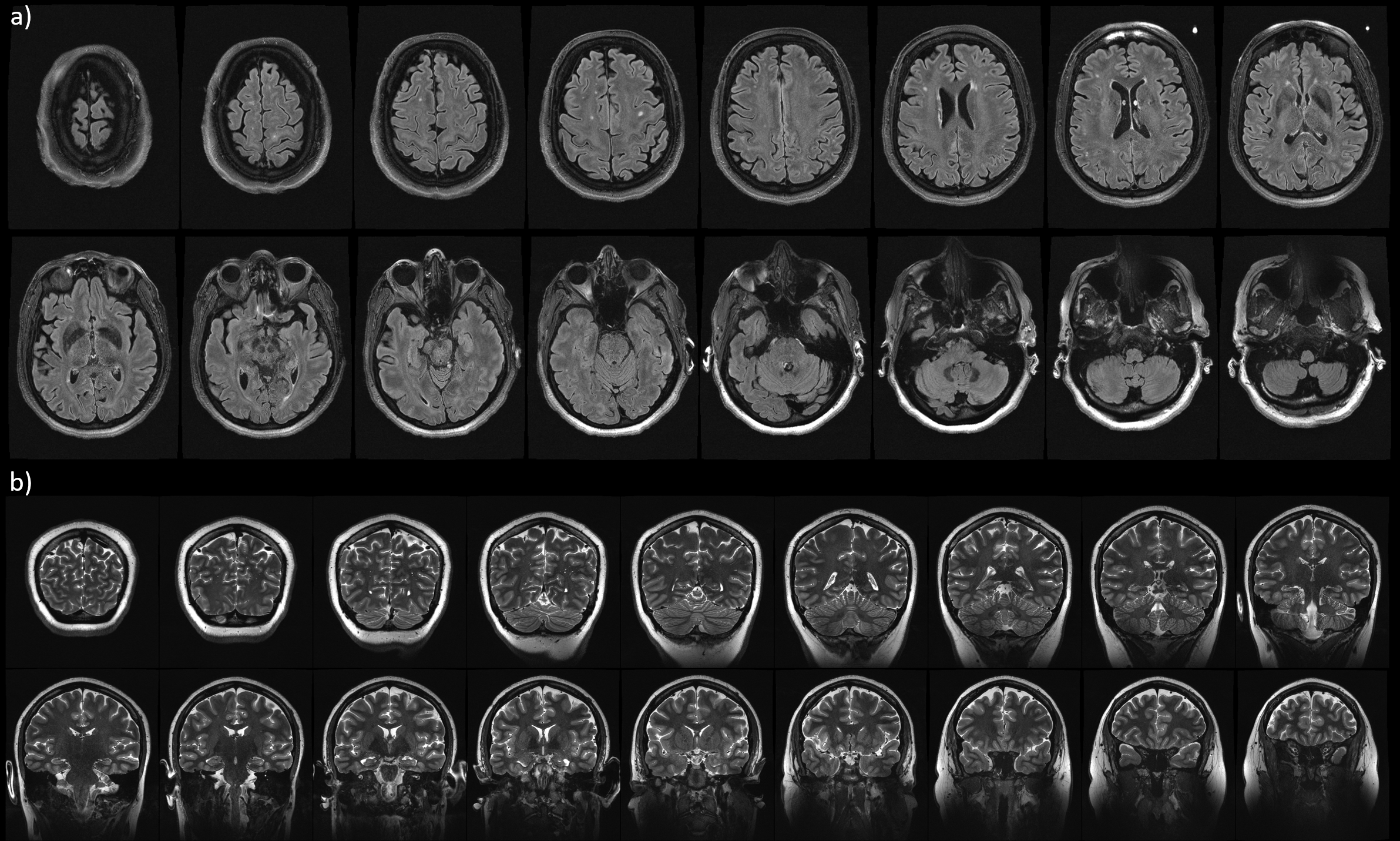
Figure 5: a) T2-FLAIR and b) T2-TSE images collected on two subjects. T2-FLAIR parameters: TR/TE = 14s/99ms; TA = 12 min; 0.75mm x 0.75mm x 1.5mm. T2-TSE parameters: TR/TE = 10s/61ms; TA = 8 min; 0.375mm x 0.375mm x 1.5mm.
DOI: https://doi.org/10.58530/2023/1057