0757
Selective Shielding for RF Energy Harvesting Without B1 Interference1ETH Zürich, Zurich, Switzerland, 2ETH Zürich, Zürich, Switzerland
Synopsis
Keywords: New Devices, New Devices, RF Harvesting; Wireless energy;
In this abstract we present a solution for harvesting RF excitation pulses in MRI while suppressing interference caused by the harvesting system, which is otherwise known to be an issue. This approach to RF harvesting offers an alternative for powering circuitry that needs to be within the field of view free from cables and without dedicated energy transmission.
Introduction
In-bore devices in MRI are becoming increasingly common in both commercial MRI and in MRI instrumentation research and serve a range of purposes such as physiological monitoring or motion tracking. These devices rely on cables or lithium based batteries for power: Cables can however sometimes cause artefacts due to EMI or become hurdles in user workflows, while batteries normally contain magnetic materials and may cause static field artefacts. Wireless power transfer in MRI has been investigated and has potential for delivering impressive amounts of power, but implies a dedicated set of hardware for transmission and may also have adverse effects on imaging SNR as well as SAR1,2. Energy harvesting of RF pulses has been suggested as an alternative power source for in-bore electronics and presents a solution that can be made wireless and without dedicated energy transmission hardware3-6. Powerful RF pulses make MRI particularly well suited for RF harvesting and authors have reported output power levels around 100 mW for receiver form factors of a few cm6. Previous work on this topic has however found that RF harvesting systems produce significant image artefacts when performing concurrent imaging and harvesting due to perturbations in the RF, or B1, field caused by the harvester3,5,6. Beyond imaging artefacts, it is also possible for these perturbations to locally alter the SAR, which may raise safety concerns.In this work we demonstrate a method for suppressing these field perturbations, allowing for RF harvesting while greatly reducing artefacts, even when harvesting within the field of view.
Methods
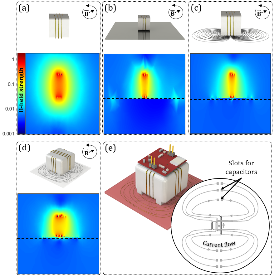
RF harvesting is performed by induction in a three-turn coil with a cross-section of 3x2 cm which is wound around a 3D-printed body. The harvester is designed to sit on the surface of the the subject, similar to surface coils, but with the coil upright. To prevent field perturbations caused by the harvester we employ a shielding technique that is based around trying to mimic the shielding properties of a continuous sheet of conductor placed between the harvester and the subject. While such a sheet solves the issue of B1 perturbations caused by the harvester, eddy currents induced directly by the B1 or the scanner gradients are still permitted to flow. To create a shield that selectively shields7 the harvester field, current in the shield is constrained to the corresponding pattern:The currents that the harvester produces in an ideal, continuous shield are modelled through simulation8 and a set of discrete conductor loops are outlined along the resulting current paths. For best shielding performance, a large number of individual loops should be used (1(b)), while it in practice however is necessary to use a smaller number due to manufacturing complexity. Symmetric pairs of loops are connected to form figure-eight shapes, which suppress coupling to the homogeneous B1 field by virtue of their antisymmetry. High-pass filtering by series capacitors prevents interaction with the gradient fields. The realized system uses two perpendicular harvesters with individual shields in a multiple-layer PCB which allows for harvesting of circularly polarized fields5. The circularly polarized harvester and an illustration of the selective shielding concept can be found in Figs. 1 (d) and (e).
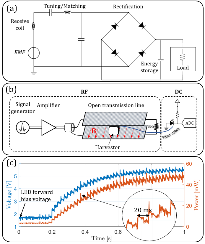
A full bridge rectifier based on Schottky diodes is employed for RF to DC conversion and a low-pass filter is used to produce a steady DC output. For lab tests, a power amplifier and an open stripline transmission line were used to produce pulsed RF fields. To avoid interference caused by cables, the output power was measured using a calibrated fiber optical circuit based on an LED being included in the rectifier load. The circuitry, the lab setup and a bench measurement of power are illustrated in Fig. 2.
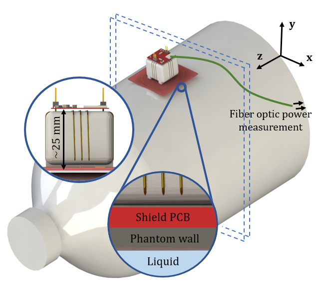
For in-bore evaluation of the harvester and shield, the system was placed on a phantom which was imaged with SE and GRE sequences at 3T without, with continuous and with selective shielding while simultaneously measuring DC power output, as illustrated in Fig. 3. The sequence parameters used were TR=168 ms, TE=4.5 ms and α= 90.
Results
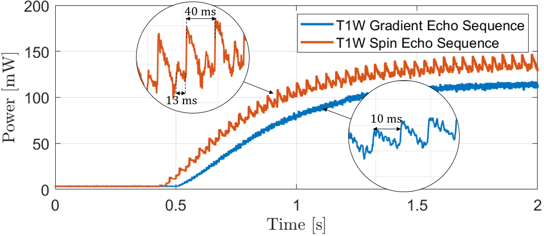
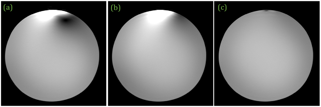
In Fig. 2 (c) bench measurements of power are shown with an arbitrary pulse type and in Fig. 4 the same type of measurements are shown for in-bore experiments with medical imaging sequences, showing how power output depends on RF pulses and sequence timing. Power levels in the order of 100 mW are recorded. In Fig. 5 we display the effects of shielding versus not shielding the harvester. In (c), with selective shielding, the artefact previously visible is strongly reduced.Discussion
According to the presented results, selective shielding is an effective means of suppressing harvester RF perturbations. We report output power in the order of 100 mW during standard sequences, being mindful that levels of instantaneous output power depend on the sequence used. For applications that rely on steady and higher power DC supply, rectifier efficiency, power management and energy storage could come to play an important role.This method has potential to prevent image artefacts as well as changes to local SAR while performing concurrent MR imaging and RF harvesting. The technology holds promise for all applications that require limited amounts of wireless power inside the imaging volume.
Acknowledgements
No acknowledgement found.References
1: Kelly Byron, Fraser Robb, Pascal Stang, Shreyas Vasanawala, John Pauly,and Greig Scott. An rf-gated wireless power transfer system for wireless mri receive arrays. Concepts in Magnetic Resonance Part B: Magnetic Resonance Engineering, 47(4):e21360, 2017.
2: Kelly Byron, Simone A Winkler, Fraser Robb, Shreyas Vasanawala, JohnPauly, and Greig Scott. An mri compatible rf mems controlled wireless power transfer system. IEEE transactions on microwave theory and techniques,67(5):1717–1726, 2019.
3: Kelly Byron, Fraser Robb, Shreyas Vasanawala, John Pauly, and GreigScott. Harvesting power wirelessly from mri scanners. In Proceedings of the International Society for Magnetic Resonance in Medicine, volume 27,page 1535, 2019.
4: Aasrith Ganti, Tracy Wynn, and Jenshan Lin. A novel energy harvesting circuit for rf surface coils in the mri system. IEEE Transactions on Biomedical Circuits and Systems, 15(4):791–801, 2021.
5: Pavel S Seregin, Oleg I Burmistrov, Georgiy A Solomakha, Egor I Kretov, Nikita A Olekhno, and Alexey P Slobozhanyuk. Energy-harvesting coil for circularly polarized fields in magnetic resonance imaging. Physical Review Applied, 17(4):044014, 2022.
6: Madhav Venkateswaran, Krishna Kurpad, James E Brown, Sean Fain, and Daniel van der Weide. Wireless power harvesting during mri. In 2020 42nd Annual International Conference of the IEEE Engineering in Medicine & Biology Society (EMBC), pages 1469–1472. IEEE, 2020.3
7: CP Bidinosti and ME Hayden. Selective passive shielding and the faraday bracelet. Applied Physics Letters, 93(17):174102, 2008.
8: CST Microwave Studio. https://www.3ds.com/products-services/simulia/products/cst-studio-suite
Figures