0754
Doppler radar signal integrity investigation for in-bore vital sensing applications1Stanford University, Palo alto, CA, United States
Synopsis
Keywords: Hybrid & Novel Systems Technology, RF Arrays & Systems, motion sensing
This study investigates complex baseband doppler radar signal integrity with linear and phase demodulations to confirm feasibility for in-bore MRI vital sensing applications.Introduction
Doppler radar at microwave frequencies has been of interest in noncontact vital sensing applications for decades1. Recent study2 demonstrated feasibility of vital sensing within the MRI bore using continuous wave (CW) doppler radar that consumes less power and operates independently of the MRI system. To foster understanding of complex baseband radar signals within the bore, we investigate systematically acquired sensing data at 2.4GHz with different antenna polarizations on a testbench, and in-bore volunteer sensing data using conventional linear and non-linear (phase) demodulations. We characterize these standard demodulation approaches to confirm feasibility of in-bore MRI vital sensing applications using CW doppler radar.Methods
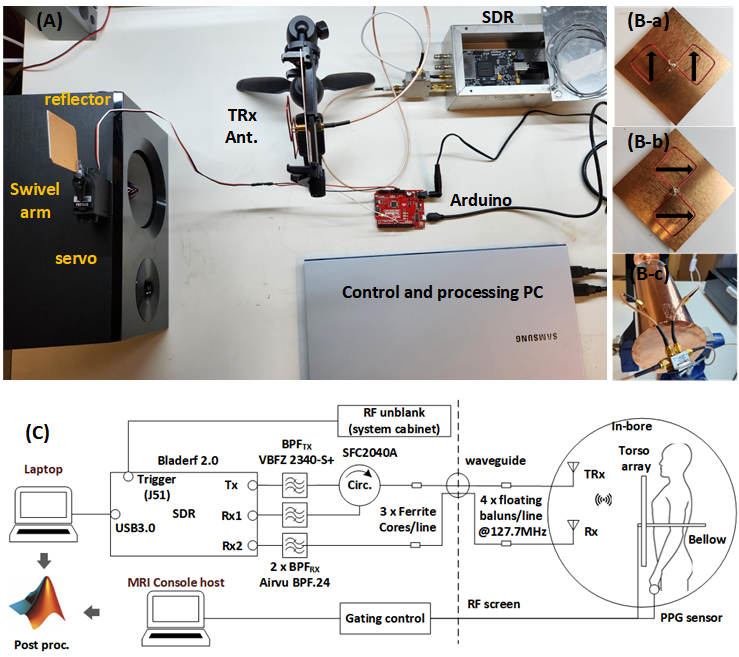
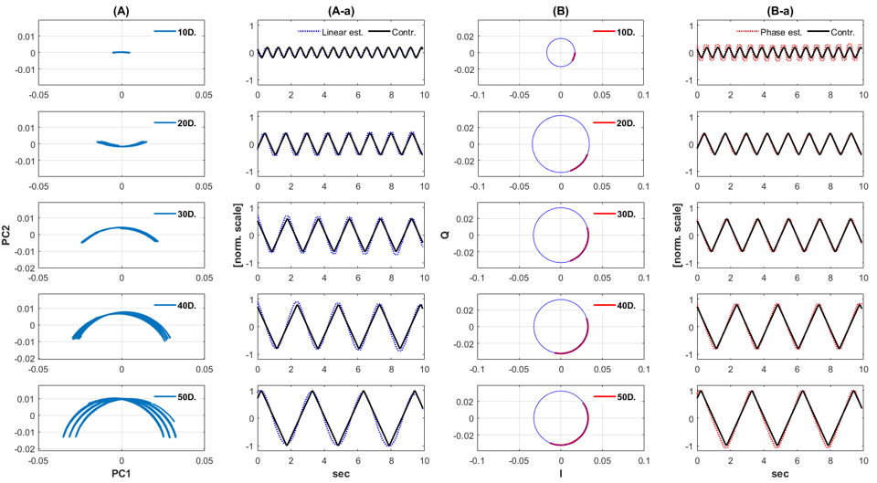
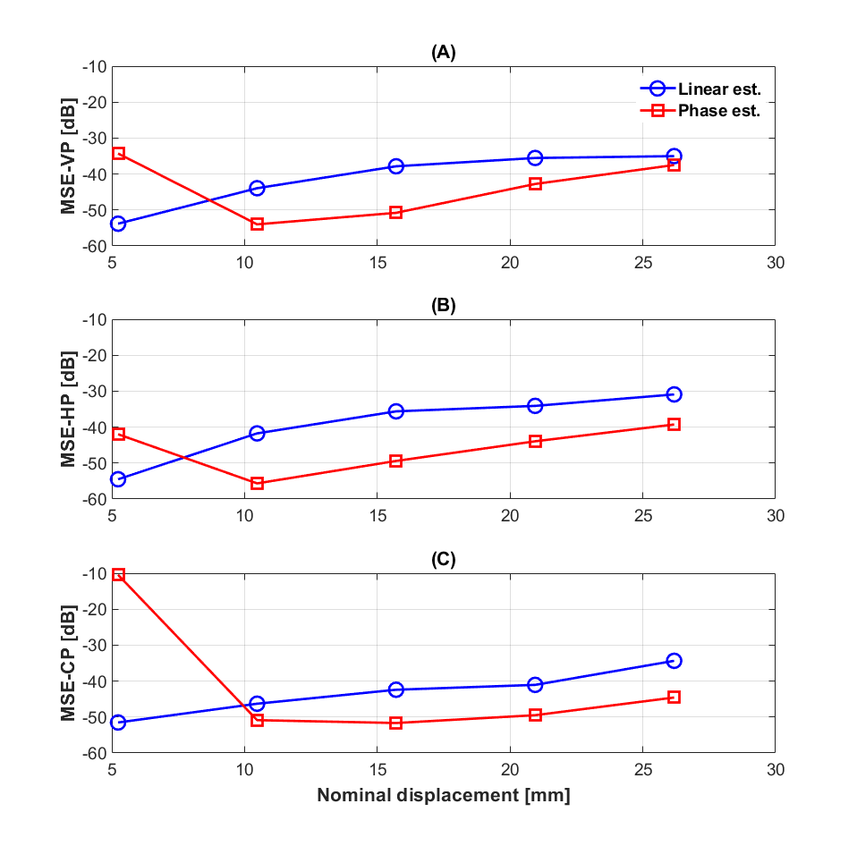
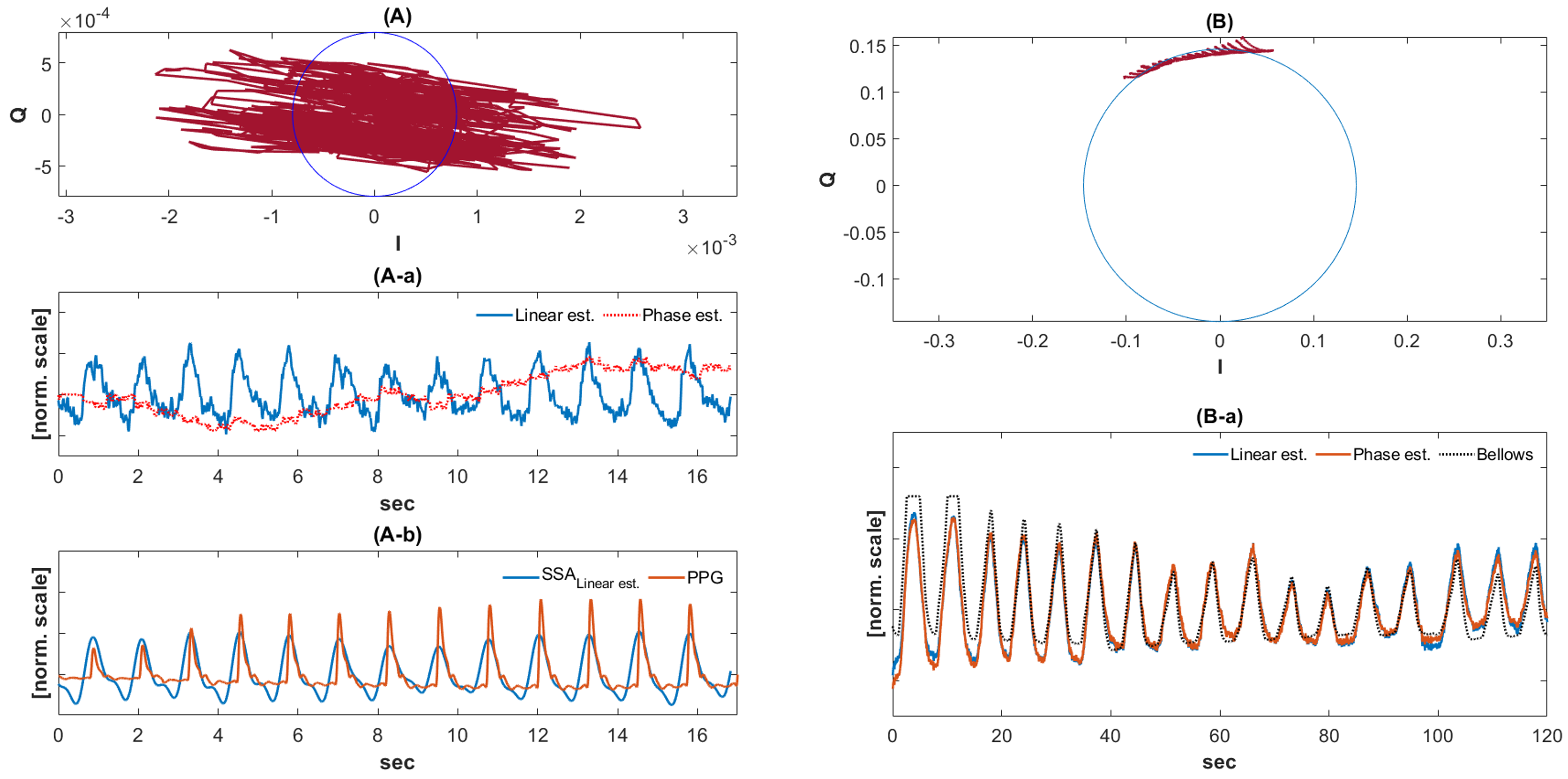
To assess radar signal integrity, a servo system (HS-422, Hitec) precisely controlled displacement scale with a reflector (5x5 cm2 copper patch) mounted on a swivel as in Figure 1 (A). The servo position angle and swing frequency were commanded by an Arduino. Each swing scale from 10 to 50-degrees in 10-degree steps produced displacements from 5.2mm (0.04λ@2.4GHz) to 26mm (0.21λ@2.4GHz) with 5.2mm increments at the center of reflector. These reflector movements were exposed to the radar antenna located 20cm away. The SDR (bladerf2.0, Nuand) was operated at 2.4GHz in single channel continuous wave mode. Subsequent radar parameter setups matched a previous study2. For each displacement scale, the complex radar data was acquired for 10s and repeated with three different antenna polarizations: vertical, horizontal, and circular, as in Figure 1 (B-a,b,c). Each data set was processed by linear and phase demodulation. Linear demodulation finds the rotation via PCA to align the time-series along the pure real axis. Phase demodulation instead attempts a fit to a circle for quantitative group delay displacement changes3. DC offset correction4 was performed prior to each phase calculation to compensate for Tx leakage and static clutter. Signal integrity was assessed by calculating Mean Squared Error (MSE) of the demodulated time series relative to the control signal. The radar-based volunteer data acquired on a testbench and within an MRI were processed with two demodulations and compared to ECG on a test-bench, and to PPG and bellows within the MRI bore. For the heartbeat signal processing, singular spectrum analysis (SSA)5 removed signal noise. In-bore setup is shown in Figure 1 (C), and vital data were retrospectively acquired.Results
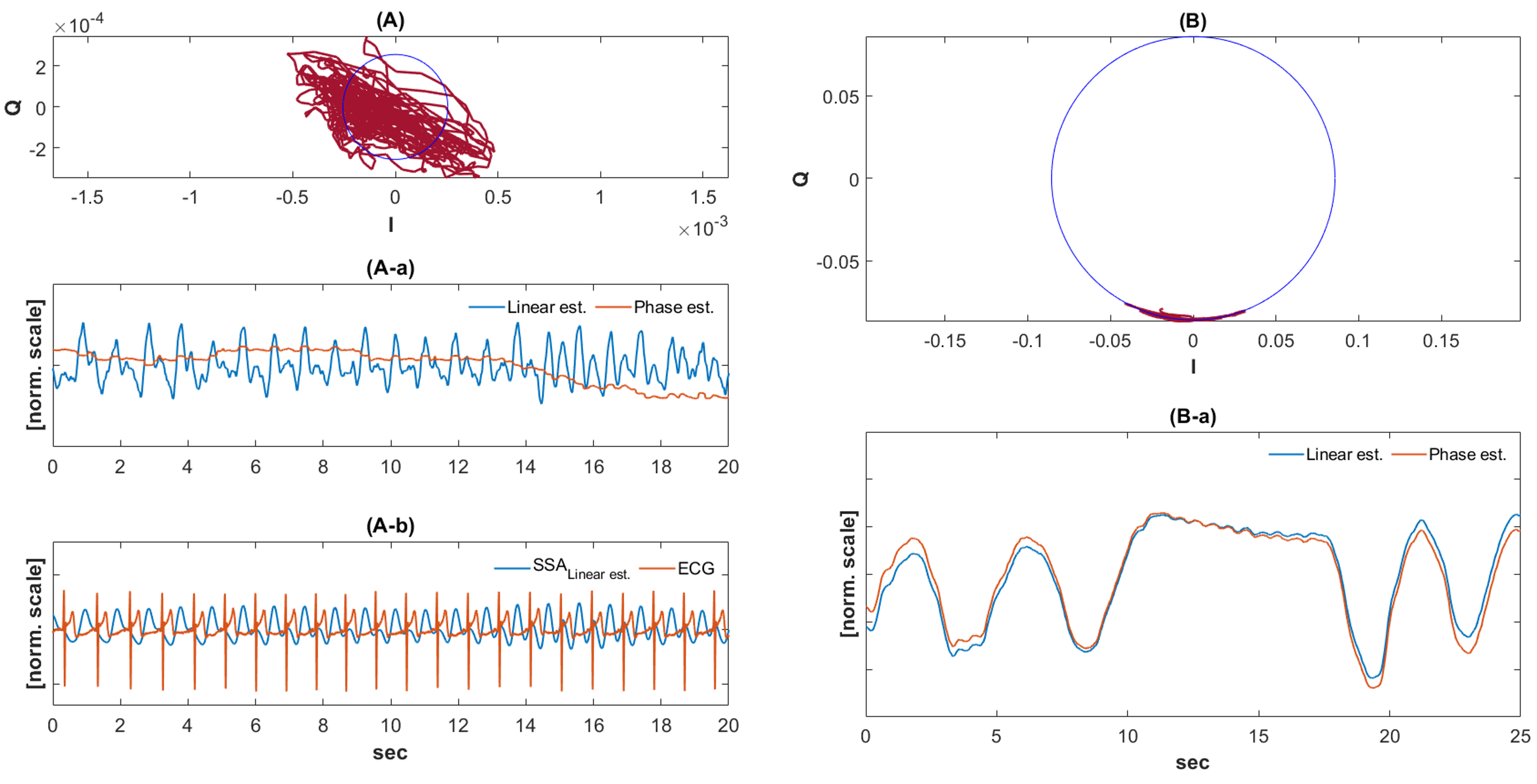
Figure 2 shows measured radar signal evolutions as a function of displacement scale (10Deg – 50Deg) using linear (A columns) and phase (B columns) demodulation. The blue solid lines in (A) represent decomposed principal components (PCs) and the blue dotted lines correspond to the time series of the largest variance PC (A-a). Similarly, (B) and (B-a) show DC offset corrected complex basebands (red solid line) in polar coordinates and the corresponding phase calculated time series (red dotted line), respectively. Black sold lines in (A-a, B-a) represent true servo control signals. The overall amplitude and frequency of the radar time series resulted in a good match to control signals at each displacement scale. However, there are noticeable discrepancies in the first row of Figure 2 (B-a) and in the several rows at higher displacements of Figure 2 (A-a). Error increases at higher displacements with linear demodulation, whereas the opposite occurs with phase, suggesting a preferable demodulation scheme depending on displacement scale. MSE curves in Figure 3 support these observations with three different antenna polarizations. Figures 4 & 5 show the complex data demodulation results of adult heartbeat (A column) and a breathing sequence (B column) measured on a testbench (Figure 4) and inside an MRI (Figure 5), respectively. The heartbeat IQ data in Figure 4 (A) falls off an arc, behaving in a linear fashion. Consequently, the phase-estimated time series has obscured signal peaks (red line in Figure 4 (A-a)), but the linear estimation clearly delineates signal peaks (blue line in Figure 4 (A-a)). These peaks show a good match with the synchronized ECG (blue line in Figure 4 (A-b)). In contrast, breathing data in Figure 4 (B) traces an arc and the corresponding time series with both linear and phase demodulation results in a clear combination of free breathing and breath-holding as in Figure 4 (B-a). The in-bore complex data in Figure 5 shows similar signal behavior. In Figure 5 (A-a) the linear estimation of heartbeat delineates signal peaks, but the phase does not because of the off-arc trace. In Figure 5 (B-a) both demodulations resulted in a clear breathing pattern and confirm excellent match with the MRI system bellows over 2 minutes.Discussion and Conclusion
Complex radar signal integrity was investigated with two fundamental demodulation approaches for in-bore sensing applications. We confirm that linear estimation is preferable in small displacement sensing, whereas DC offset corrected phase fits in relatively large movement scales. The rough estimate for this demodulation boundary is approximately at 0.08λ which is similar in value to an earlier study6. This scenario holds for in-bore sensing, where the antenna proximity to a subject causes dominant reflected waves directly from the subject surface at short range. In future, with integrated in-bore radar antennas, DC offset calibration may be carried out for optimum demodulation of real time in-bore vital sensing.Acknowledgements
We thank GE Healthcare for research support, and received funding from NIH grants R01 EB019241, U01EB029427, R01EB012031, U01EB026412References
1. C. Li, V. M. Lubecke, O. Boric-Lubecke and J. Lin, "A Review on Recent Advances in Doppler Radar Sensors for Noncontact Healthcare Monitoring," in IEEE Transactions on Microwave Theory and Techniques, vol. 61, no. 5, pp. 2046-2060, May 2013
2. W. Lee, K. Ryu, F. Robb, J. Pauly, S. Vasanawala, S. Greig, “Noncontact in-bore cardiopulmonary sensing using CW doppler radar”, ISMRM2022, #5024
3. Olga Boric-Lubecke; Victor M. Lubecke; Amy D. Droitcour; Byung-Kwon Park; Aditya Singh, "Ch.5 CW HOMODYNE TRANSCEIVER CHALLENGES" in Doppler Radar Physiological Sensing, IEEE, 2016, pp.21-38
4. XU, W., GU, C., LI, C., & SARRAFZADEH, M. (2012). Robust Doppler radar demodulation via compressed sensing. Electronics Letters, 48(22), 1428–1430.
5. S. Sanei and H. Hassani, “Singular Spectrum Analysis of Biomedical Signals”, 2015.
6. Vergara, Alex & Lubecke, Victor & Høst-Madsen, Anders. (2007). Quadrature Demodulation with DC Cancellation for a Doppler Radar Motion Detector.
Figures