0750
Real-time Needle Tracking Under 0.55T MRI Using Current Controlled B1 Field Artifacts1National Heart Lung and Blood Institute, National Institutes of Health, Bethesda, MD, United States, 2Institute of Biomadical Engineering, Bogazici University, Istanbul, Turkey, 3Transmural Systems, Andover, MA, United States
Synopsis
Keywords: Interventional Devices, Interventional Devices
In this work, an interventional device tracking method under high performance 0.55T MRI is presented using a custom designed nitinol needle. Ultra-thin miniature solenoid coil markers were designed and printed on the needle using conductive ink. A negative contrast is created around the needle by applying an alternative current to the markers and hence introducing an offset to the B1 field. A signal generator circuit is designed for supplying and controlling the AC signal and the visibility of the needle is tested under MRI with in-vitro experiments during a real time b-SSFP sequence.INTRODUCTION
MRI is a good candidate for image-guided interventions because of its excellent soft tissue contrast, fast multiplanar imaging, ability to provide function/physiological information, and freedom from ionizing radiation1. Performing interventional procedures under MRI guidance requires custom-designed interventional devices due to potential safety problems caused by radio frequency (RF) transmission and high magnetic field, and difficulties in visualizing commercially-available metallic interventional devices. Increasing the visibility of MR-safe interventional devices is usually achieved by placing active2,3, passive4 or resonant5 markers on the device. Glowinski et al. introduced another method for device tracking by applying a direct current (DC) to the conductive wires placed on a catheter creating a negative contrast on the image6. Their method allows the user to control the artifact size by controlling the applied current and it can provide safe and easy device tracking for MR-guided interventions if implemented unobtrusively.METHODS
Ultra-thin (20 µm) miniature coil markers were designed and placed on MR-compatible nitinol (Memry Corp CT) needle prototypes (length: 10 cm, outer diameter: 1 mm) using a conductive ink printer system that was built in our earlier work2. Three markers were placed on the needle at the distal tip, the middle, and the proximal end of the needle to provide an accurate tip location and insertion depth information. Transmission lines and marker solenoid coils were printed on heat shrink polyester tubes (Nordson Medical, MA )(25 µm wall thickness) using silver conductive ink (AG-500, Kayaku Advanced Materials, MA) (20 µm ink thickness ) as shown in figure 1. Markers and conductive transmission lines were printed on two separate layers. The localized magnetic field created by the coil markers can provide distinct negative contrast around the markers.A signal generator electronic circuit composed of a microcontroller (Arduino Nano 33 IoT), a signal generator module (AD9833, Analog Devices, MA), and non-magnetic MRI-compatible batteries (GM-NM103450-PCB, Power Stream Technologies, UT), was designed for supplying the necessary periodic current for the current controlled markers (figure 2). The frequency and the amplitude of the applied current is controlled by using the signal generator circuit and the amplitude of the current is limited to a maximum of +/-50mA (100 mA peak to peak).
The custom needle prototype was placed in an ASTM gel phantom7 and tested using a high-performance 0.55T MRI scanner(MAGNETOM Aera, Siemens Healthcare, Erlangen, Germany) for MRI visibility and artifact size control using the signal generator circuit during in-vitro experiments. An AC signal was used here, instead of DC as previously used to be able to create controllable artifacts by maximizing the difference between externally applied offset to the consecutive gradients of the real-time b-SSFP sequence (TE/TR: 2.52/5.04 ms, flip angle: 750, FOV: 399 x 399 mm, bandwidth: 300 Hz/Px, matrix: 240 x240, slice thickness: 8mm).
RESULTS
Figure 3 shows the effects of the alternative current frequency on the marker artifacts with respect to the TR value of the sequence. The maximum artifact size is achieved when a current is applied to the markers is 100Hz, which is half the repetition frequency of the sequence (198Hz). The ideal timing of the applied current with respect to the b-SSFP pulse sequence is given in figure 4.Figure 5 shows the effect of the alternative current amplitude on the needle marker artifact size. Using the signal generator circuit, the marker artifact size can be adjusted or completely turned off.
DISCUSSION
Designing novel custom devices that are safe and trackable under MRI is crucial for the improvement and success of MR-guided interventions. The device tracking method introduced in this work is independent of the scanner’s field strength or Larmour frequency, does not require a connection to the scanner’s RF chain, an external software, or image postprocessing. It enables the user to control the marker artifact size and it can be turned off completely allowing physicians to see the anatomical image underneath the markers when needed. Applying conductive ink-printed markers is an unobtrusive device modification because it does not increase the outer diameter or spoil the outer profile of the interventional device significantly. Markers can be placed onto any MRI-safe interventional device and the same signal generator circuit can be used for creating controllable tracking artifacts during real-time MR-guided procedures. These advantages show that using current applied markers for device tracking under MRI is a promising method for the improvement of MR-guided interventions.CONCLUSION
In this work, thin-film printed coil markers were designed using conductive ink and placed on a custom nitinol needle. A signal generator circuit was employed for supplying the AC signal instead of a continuous or a transient DC signal to the markers maximizing the marker artifact size. MRI visibility of the needle markers and control of marker artifact size using the signal generator circuit were confirmed during in-vitro experiments under 0.55T scanner.Acknowledgements
This work is supported by National Heart, Lung, and Blood Institute, Grant/Award Number: Z01-HL006041References
- Rogers, Toby, et al. "Interventional Cardiovascular Magnetic Resonance: State-of-the-Art Review [Pending]," Circulation: Cardiovascular Imaging (2023).
- Yildirim, Dursun Korel, et al. "A 20‐gauge active needle design with thin‐film printed circuitry for interventional MRI at 0.55 T." Magnetic resonance in medicine 86.3 (2021): 1786-1801.
- Yildirim, Dursun Korel, et al. "An interventional MRI guidewire combining profile and tip conspicuity for catheterization at 0.55 T." Magnetic Resonance in Medicine (2022).
- Settecase, Fabio, et al. "Magnetic resonance–guided passive catheter tracking for endovascular therapy." Magnetic Resonance Imaging Clinics 23.4 (2015): 591-605.
- Kaiser, Mandy, et al. "Resonant marker design and fabrication techniques for device visualization during interventional magnetic resonance imaging." Biomedical Engineering/Biomedizinische Technik 60.2 (2015): 89-103.
- Glowinski, Arndt, et al. "Catheter visualization using locally induced, actively controlled field inhomogeneities." Magnetic resonance in medicine 38.2 (1997): 253-258.
- ASTM F2182- 19e2. Standard Test Method for Measurement of Radio Frequency Induced Heating On or Near Passive Implants During Magnetic Resonance Imaging. West Conshohocken, PA: ASTM International; 2019. Available at: https://www.astm.org.
Figures
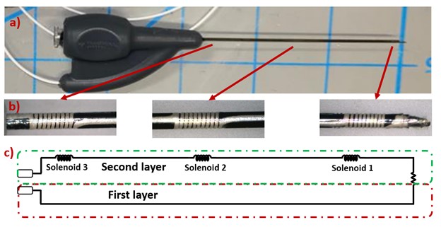
Fig. 1. a) Custom design nitinol needle b) close-up to three coil markers on the needle c) schematic representation of current path on the needle
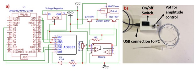
Fig. 2. a) Schematics of signal generator circuit b) signal generator circuit connected to the needle prototype
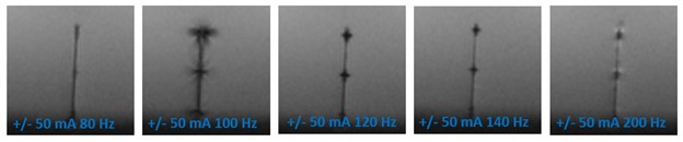
Fig. 3. Needle Marker artifact size comparison while +/- 50 mA AC signal was being applied in different frequencies (80Hz to 200Hz) during a b-SSFP sequence with 5 ms TR value (repetition frequency: 200Hz)
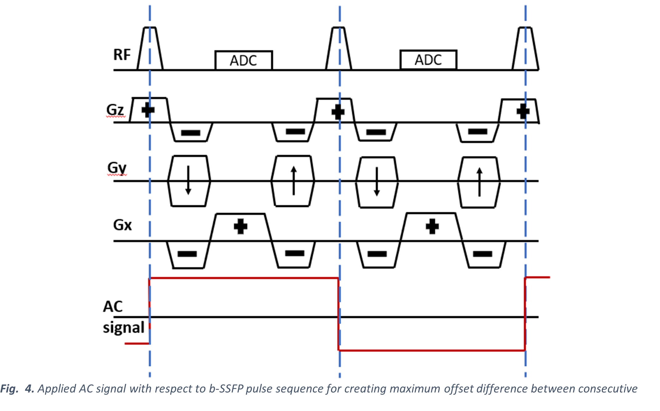
Fig. 4. Applied AC signal with respect to b-SSFP pulse sequence for creating maximum offset difference between consecutive repetitions
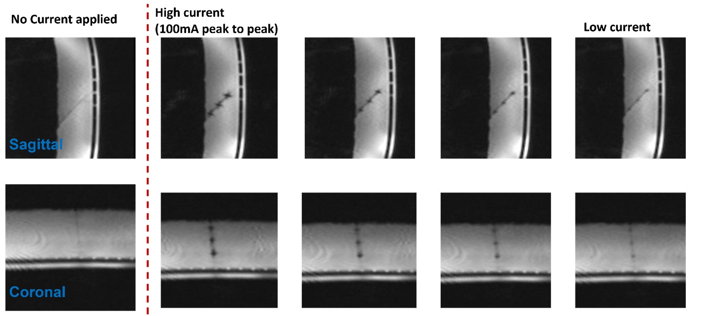
Fig. 5. Sagittal and coronal images of the needle marker artifact sizes with respect to the amplitude of the applied current