0746
The MRDust: An Implantable Neural Interface Powered via Focused Ultrasound with Data Communication via MR Image Modulation
Biqi Rebekah Zhao1, Yuhan Wen1, Alexander Chou1, Elad Alon1, Rikky Muller1, Chunlei Liu1, and Michael Lustig1
1Department of Electrical Engineering and Computer Sciences, University of California, Berkeley, Berkeley, CA, United States
1Department of Electrical Engineering and Computer Sciences, University of California, Berkeley, Berkeley, CA, United States
Synopsis
Keywords: New Devices, Neuroscience
We propose a new device for neuroscience studies: the MRDust, a sub-mm wireless programmable neural recording mote with on-device memory and compute. It receives power via focused ultrasound, records neural signals in burst mode, and uses a micro-coil to perturb local magnetic fields to achieve data uplink via dynamic MRI signal modulation. We demonstrate proof-of-concept experiments in which digital information is encoded in images of an SE-EPI dynamic sequence, and in which a piezoelectric harvester can harvest enough ultrasonic power to sustain device operation, and receive control signals through amplitude modulation.Introduction
Being able to record neural activities at high temporal and spatial resolution with whole-brain coverage allows us to better understand, diagnose and treat neurological disorders, but remains a challenge1. Non-invasive methods like functional MRI offer information about brain structure/function, but exhibit low temporal resolution. Tethered devices (Utah Array2/Neuropixel3) can record in a small cortex region at high temporal resolution, but have low spatial coverage and are extremely invasive. Wirelessly powered miniaturized implants are an appealing alternative as they cause minimal tissue damage4. Unfortunately, conventional wireless power and data link modalities (RF/ultrasound) suffer significant tissue propagation loss, making it extremely difficult to reach deep brain5,6. Device localization also becomes challenging with an increased number of implants.In this work, we present a new concept called MRDust, which aims to alleviate some of the aforementioned issues by utilizing focused ultrasound for power and data downlink, and dynamic MR image modulation for data uplink. It has the potential to yield micro-sized devices that record deep brain neuronal activities at multiple sites simultaneously. Devices can be implanted in clusters in an animal brain or a human brain undergoing surgery. Here we demonstrate several proof-of-concept feasibility experiments: we show that digital information can be encoded in dynamic MRI scans by DC current modulation in a micro-coil, and that enough power can be harvested by a piezoceramic to support device operation. We designed an integrated circuit (IC) which performs power harvesting, uplink and downlink communication, which is under fabrication.
Methods
Device Overview:Each device is envisioned to contain a piezoceramic for power harvesting, a pair of electrodes to measure neural signals, and a programmable chip with compute and storage capabilities to perform neural data recording, processing and uplink communication (Figure 1a). The device operates in the following order in each recording cycle: 1) Focused ultrasound is used to power the devices and send control signals by amplitude modulation (Figure 1b). 2) Devices are signaled to record neural data in burst mode for short intervals, process them and store on-chip (Figure 1c). 3) To perform data uplink, DC current is driven through a micro-coil on-chip to modulate the local magnetic field, encoding stored data frame-by-frame by modulating voxel intensity (Figure 1d). We hypothesize that modulating the MR signal using DC currents in a micro-coil is more efficient than RF/Ultrasound communication from a micro-device.
Pulse Sequence:
Data transmission is achieved by syncing the coil current to a dynamic pulse sequence (GRE-EPI/SE-EPI) via ultrasonic downlink. By passing a DC current through the micro-coil, we generate a local magnetic field to dephase surrounding spins, resulting in diminished voxel intensity. During GRE-EPI, coil current is turned on or off throughout the TR to transmit a digital “1” or “0” respectively (Figure 2a). During SE-EPI, the coil’s current is reversed after the spin-echo to suppress refocusing of local spins when transmitting a “1”, and turned off when transmitting a “0” (Figure 2b). In both cases, digital “1” exhibits a lower voxel intensity than digital “0” (Figure 2d). Through synchronization, each micro-coil encodes digital data frame-by-frame so that neural data from each device can be localized and extracted from dynamic MR images.
Proof-of-concept:
i) The data uplink method was demonstrated with a 3T GE MR750W system (Waukesha, WI). A 2-mm double-loop coil was placed in a container with 3.3% NiCl2(aq). The coil was controlled by a Teensy3.5 microcontroller (Figure 3a). Controlled currents (100uA-800uA) were passed through the coil, and 2D-coronal images through the phantom at varying TE (12ms-100ms) were taken.
ii) To demonstrate feasibility of device miniaturization, several parts of the envisioned system were designed. A 0.7mm thick PZT-4 sheet was diced into 1.54x1.54mm2 cuboids, bonded to a flexible PCB, and encapsulated by 3.5um thick Parylene C (Figure 4a). The device was characterized by a Network Analyzer in a DI water tank while receiving ultrasonic power from a 1.18MHz transducer (Figure 4b). An IC containing a micro-coil for data uplink, a rectifier and demodulation circuit for ultrasonic energy harvesting and data downlink was designed in TSMC 28nm technology (Figure 5), and is currently being fabricated.
Results and Discussion
Simulation shows that with a 650um 10-turn coil, 100uA current and 60ms TE, 15% signal modulation can be achieved with SE-EPI (Figure 2c). Contrast can be increased by optimizing TE, or increasing coil current at the cost of power consumption. Experimental results show that in GRE-EPI, generated contrast competes with natural T2* decay (Figure 2d); this is improved by using bipolar coil current in SE-EPI. Figure 3d shows data “110101” encoded in images in an SE-EPI scan. With increased TE and coil current, better signal contrast was achieved, matching simulation results (Figure 3b,c).The PZT can harvest 95uW at the FDA limit for diagnostic ultrasound (720mW/cm2), sufficient for powering the IC. To program the mote while powering, we demonstrate amplitude modulation at 300Hz with 50% duty cycle (Figure 4d).Conclusion
We propose the concept of a wireless deep brain neural implant that harvests power from focused ultrasound and uses a micro-coil to achieve simultaneous data uplink at multiple sites via dynamic MRI. We conducted proof-of-concept experiments to demonstrate data encoding feasibility of a micro-coil, and energy harvesting capability of a piezo.Acknowledgements
The authors would like to thank the sponsors of the Berkeley Wireless Research Center and TSMC university shuttle program for chip fabrication. We thank the following funding source: National Institutes of Health (NIH) grant R01MH127104.References
- A. P. Alivisatos, A. M. Andrews, E. S. Boyden, M. Chun, G. M. Church, K. Deisseroth, J. P. Donoghue, S. E. Fraser, J. Lippincott-Schwartz, L. L. Looger, S. Masmanidis, P. L. McEuen, A. V. Nurmikko, H. Park, D. S. Peterka, C. Reid, M. L. Roukes, A. Scherer, M. Schnitzer, T. J. Sejnowski, K. L. Shepard, D. Tsao, G. Turrigiano, P. S. Weiss, C. Xu, R. Yuste, and X. Zhuang, “Nanotools for Neuroscience and Brain Activity Mapping,” ACS nano, 26-Mar-2013.
- E. M. Maynard, C. T. Nordhausen, and R. A. Normann, “The Utah Intracortical Electrode Array: A recording structure for potential brain-computer interfaces,” Electroencephalography and Clinical Neurophysiology, 30-Nov-1999.
- J. J. Jun, N. A. Steinmetz, J. H. Siegle, D. J. Denman, M. Bauza, B. Barbarits, A. K. Lee, C. A. Anastassiou, A. Andrei, Ç. Aydın, M. Barbic, T. J. Blanche, V. Bonin, J. Couto, B. Dutta, S. L. Gratiy, D. A. Gutnisky, M. Häusser, B. Karsh, P. Ledochowitsch, C. M. Lopez, C. Mitelut, S. Musa, M. Okun, M. Pachitariu, J. Putzeys, P. D. Rich, C. Rossant, W.-lung Sun, K. Svoboda, M. Carandini, K. D. Harris, C. Koch, J. O’Keefe, and T. D. Harris, “Fully integrated silicon probes for high-density recording of neural activity,” Nature News, 09-Nov-2017.
- J. Thelin, H. Jörntell, E. Psouni, M. Garwicz, J. Schouenborg, N. Danielsen, and C. E. Linsmeier, “Implant size and fixation mode strongly influence tissue reactions in the CNS,” PloS one, 26-Jan-2011.
- S. A. Mirbozorgi, P. Yeon, and M. Ghovanloo, ‘‘Robust wireless power transmission to mm-sized free-floating distributed implants,’’ IEEE Trans. Biomed. Circuits Syst., Jun-2017.
- D. Seo, J. M. Carmena, J. M. Rabaey, M. M. Maharbiz, and E. Alon, “Model validation of untethered, ultrasonic neural dust motes for cortical recording,” Journal of Neuroscience Methods, 07-Aug-2014.
Figures
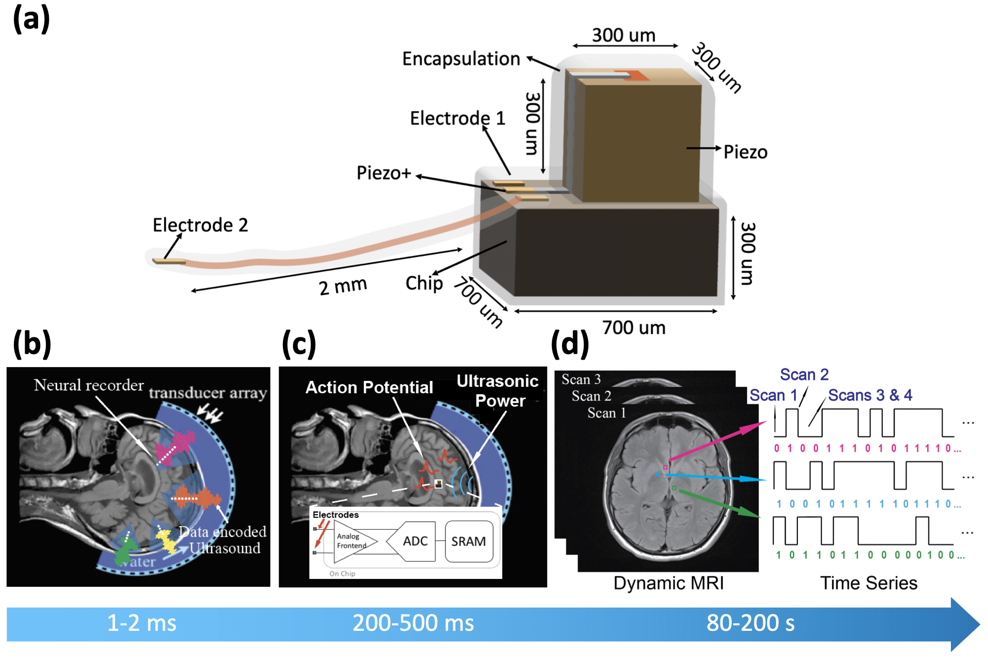
Figure 1: a) Conceptual diagram of implant. It comprises a piezo receiver, two electrodes and an IC. b) Power delivery and downlink control: MRgHIFU directs ultrasonic energy to several areas to power multiple motes at once. Downlink data is encoded in ultrasound by amplitude modulation. c) Burst recording: on command, implants record neural potential in burst mode, amplify, digitize and store them. d) Data uplink: implants encode binary data in dynamic MRI bit by bit, reading recordings from multiple motes in parallel. Blue bar shows order and duration of events in an operation cycle
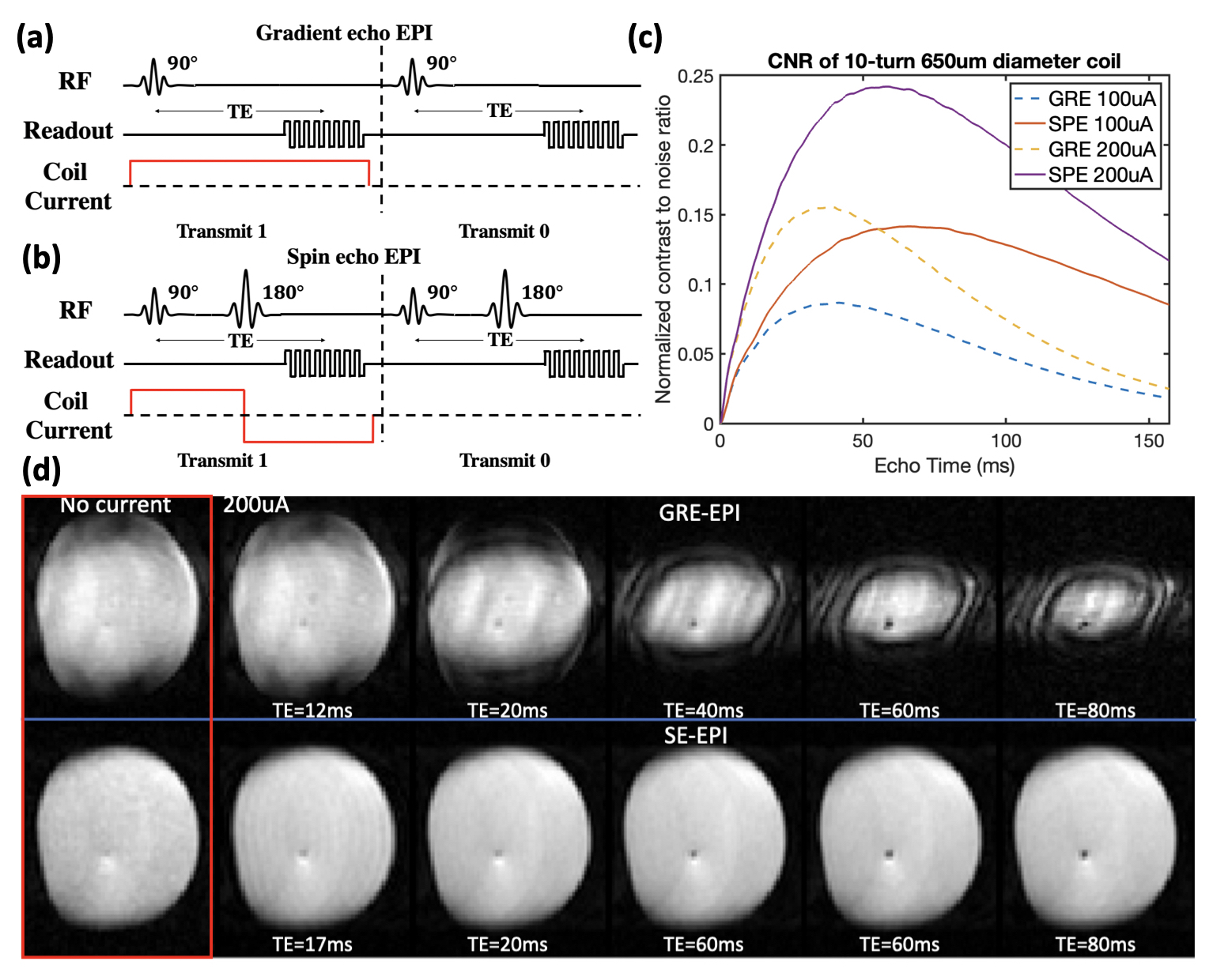
Figure 2: a,b) Coil current in-sync with GRE-EPI and SE-EPI sequence c) Simulation result of relationship between signal contrast, current and TE in GRE-EPI and SE-EPI for a 10-turn 650um coil in 2x2x2mm3 voxel d) Imaging result of signal contrast, for 4-shot GRE-EPI (TE/TR/FA = 12-80ms/500ms/65°, pixel:1.7x1.7mm2, SL:3.6mm, BW:100Hz/pixel ) & SE-EPI (TE/TR = 17-80ms/2s, pixel:1.7x1.7mm2, SL:3.6mm, BW:100Hz/pixel). In GRE-EPI signal contrast competes with T2* decay.
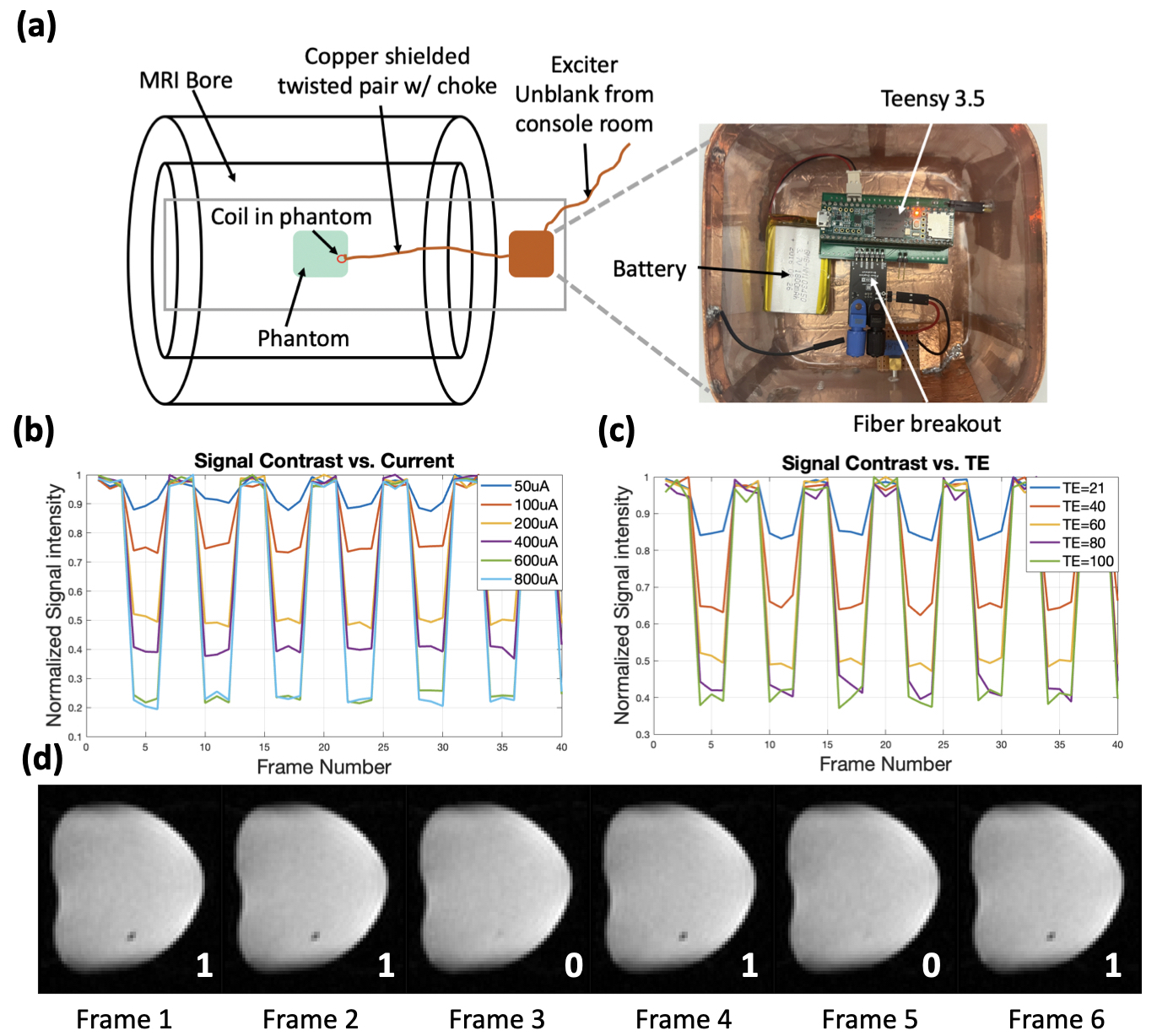
Figure 3: a) Experimental setup in scanner: coil in phantom, connected to Teensy3.5 and battery with a shielded twisted pair. Controller receives signals from the scanner via fiber. b,c) Experimental results of a 40-frame SE-EPI sequence: voxel intensity modulated by coil current. Modulation increases with longer TE and more current (TE/TR:21-100ms/500ms, pixel: 1.7x1.7mm2, SL:3.6mm, BW:100Hz/pixel). d) 6 consecutive frames from an SE-EPI scan, showing digitally encoded bits “110101” with 200uA current and 60ms TE.
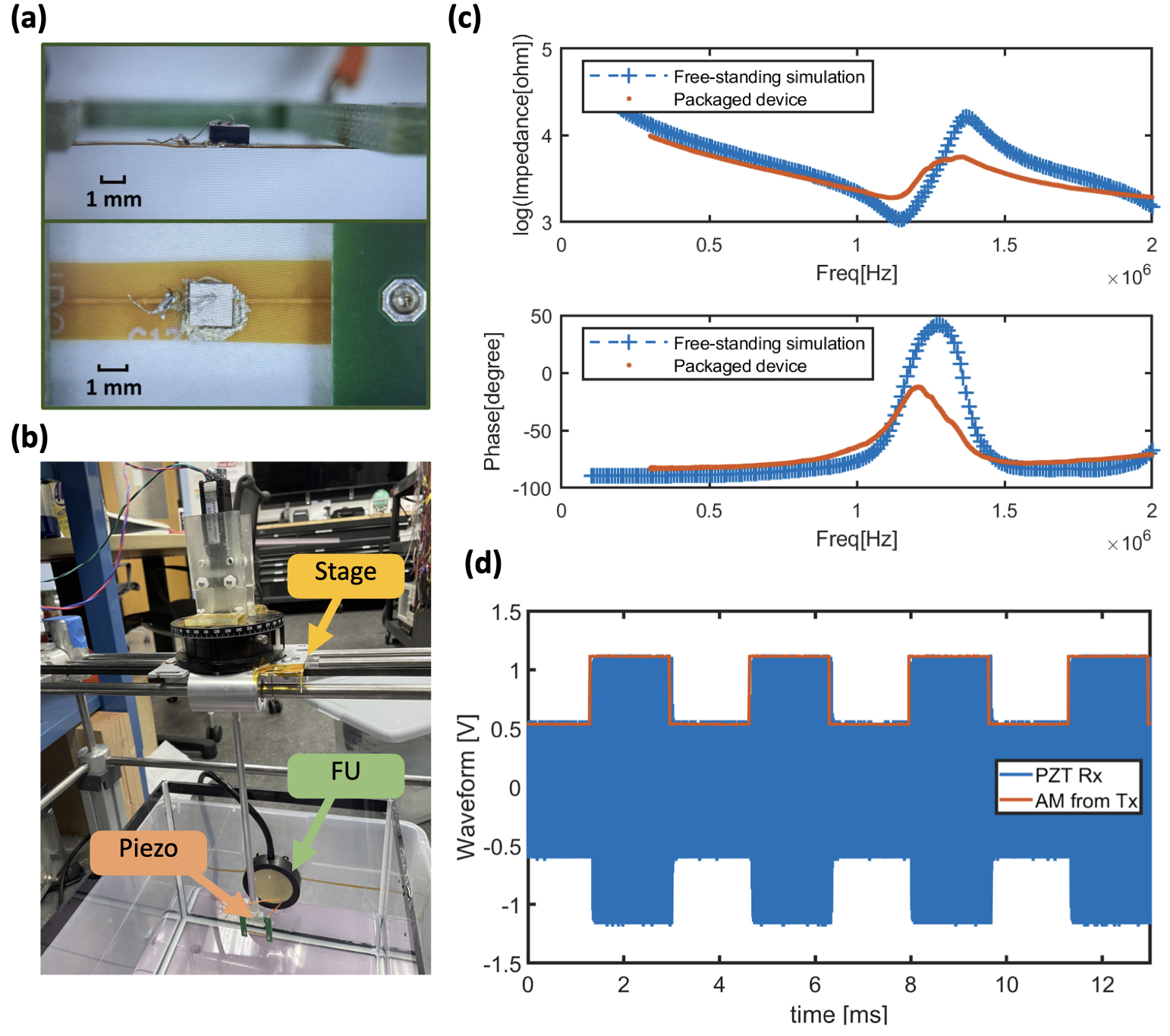
Figure 4: a) Prototype piezo wiring and packaging b) Photo of the MR-compatible focused ultrasound transducer and the ultrasonic scanning tank for piezo characterization c) Measured impedance spectroscopy of piezo d) Demonstration of amplitude modulation and the received modulated signal by piezo
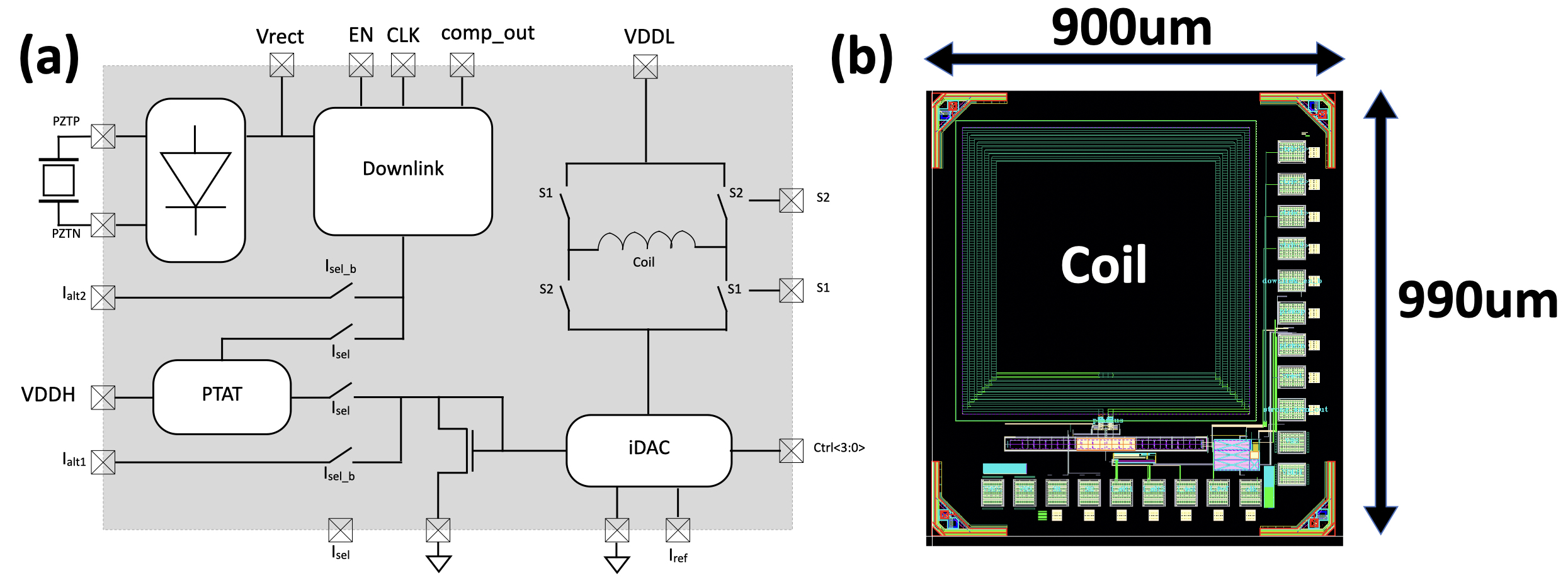
Figure 5: a) Circuit diagram of the prototype chip. It consists of a power management module with a rectifier and downlink decoder, and a current DAC that can drive 50uA-750uA current in the microcoil at 50uA step. b) Die photo of the chip. In a later iteration we will add neuronal recording frontend, ADC, and memory.
DOI: https://doi.org/10.58530/2023/0746