0727
Reduction of cryoneedle artifacts due to cryoneedle-RF coil interaction during MRI-guided cryoablation
Aiming Lu1, Guruprasad Krishnamoorthy1,2, Jacinta G Browne1, Scott M Thompson1, Daniel A Adamo1, and David A Woodrum1
1Mayo Clinic, Rochester, MN, United States, 2Philips Healthcare, Rochester, MN, United States
1Mayo Clinic, Rochester, MN, United States, 2Philips Healthcare, Rochester, MN, United States
Synopsis
Keywords: Pelvis, Artifacts, intervention
MRI-guided cryoablation is a widely used minimal invasive treatment that uses extreme cold to destroy localized diseased tissues. The cryoneedles used are expected to introduce little metal artifacts by themselves in the MRI images. However, severe artifacts along the cryoneedle shaft are sometimes observed during MRI guided cryoablations in practice, which can not only complicate the cryoablation procedures, but also potentially cause complications and negatively affect treatment outcome. This work demonstrated that the artifacts are likely due to coupling of the cryoneedles and the RF coils, and can be minimized by proper positioning of the cryoneedles, RF coils and patients.Introduction
MRI-guided cryoablation is a widely used minimal invasive treatment that uses extreme cold to destroy localized diseased tissues (1-4). MRI guidance is desirable as it allows for target tissue delineation, cryoneedle placement guidance, real-time treatment progress monitoring and treatment assessment. The cryoneedles are made of non-magnetic nickel-chromium-based superalloys known as Inconel and are expected to introduce little metal artifacts by themselves in the MRI images. However, severe artifacts along the cryoneedle shaft are sometimes present during MRI guided cryoablations in practice, which can obstruct the visualization of the cryoneedle placement and the iceball boundary as these artifacts can also appear as a signal void or a low signal region. As a result, the artifacts can not only complicate the cryoablation procedures, but also potentially cause complications and negatively affect treatment outcome. The purpose of this work is to investigate the cause of these artifacts and potential strategies to minimize them.Materials and methods
MRI guided cryoablations were performed on a 1.5T Ingenia scanner (Philips Healthcare, Netherlands) using the Visual-ICE MRI system (Boston Scientific, Marlborough, MA) and cryoneedles (IceSeed/IceRod MRI, 17 Gauge). IRB approval was obtained for patient studies. Ex-vivo cryoablation studies were performed using porcine tissue samples. A dStream Flex M loop coil and the posterior coil integrated in the patient table were used for data acquisition in both patient and ex-vivo tissue sample studies. Figure 1 shows an example of cryoneedle artifacts during a cryoablation procedure. The artifacts obscured the visualization of the cryoneedle and also made it difficult to monitor the iceball evolution due to their similar appearance in the images. These artifacts likely come from the coupling between the cryoneedles and the RF coils when they are placed close to each other since the cryoneedles are metallic. To investigate the dependence of the cryoneedle artifacts on the relative positioning of the cryoneedle to the coils, tissue sample experiments were performed using different pulse sequences for imaging. A cryoneedle was inserted horizontally ~10cm into the tissue placed on the patient table. Unless otherwise stated, the cryoneedle was disconnected from the mobile connection panel (MCP). MR imaging was performed with the following coil/cryoneedle configurations: 1. The tissue sample was placed on the patient table with a layer of procedure underpad. An IceRod cryoneedle was inserted into the tissue and ~3cm from the patient table. The loop coil was placed on top of the tissue sample and ~3cm from the cryoneedle. 2.Same as configuration 1 except the IceRod was replaced with a IceSeed. 3. Same as configuration 2 except the loop coil was removed and only the posterior coil was used for data acquisition. 4. Same as configuration 2 except with the cryoneedle connected to the MCP. 5. Same as configure 2 except the separation between the tissue sample and the patient table was increased by 4 cm using a pad. 6. Same as configuration 5 but with the cryoneedle connected to the MCP. The experiments were repeated with different cryoneedle insertion locations into the tissue sample. MR imaging was performed using several typically used sequences, including a T2-weightedTSE sequence (TE/TR: 70ms/971ms, ETL: 22), a proton density-weighted (PD-W) TSE sequence (TE/TR: 25ms/3800ms, ETL: 22). To reduce metal artifacts, a 3D UTE with a TE of 0.14 ms was also used.Results and discussion
With the tissue placed closed to the patient table and consequently the integrated posterior coil, severe artifacts are seen in all MR images acquired with different pulse sequences (Figure 2a-c). Changing from an IceRod cryoneedle to a IceSeed cryoneedle, connecting/disconnecting the cryoneedle from the MCP showed insignificant impact on the artifacts. Removing the loop coil did not have much impact on the artifacts either, which means the loop coil was not the source of the artifacts in this case. When the tissue sample was moved away from the posterior coil, however, the cryoneedle artifacts were minimized and the cryoneedle could be clearly visualized as negative contrast (Figure 2d). This confirmed that the coupling between cryoneedle and the posterior coil was the source of the artifacts in these experiments. Although the artifacts shown in the ex vivo experiments here were from coupling between the cryoneedle and the posterior coil, cryoneedle artifacts due to coupling between the cryoneedles and other coils (such as the loop coil) have also occurred (e.g., Figure 1). The severity of the artifacts depends highly on the relative positions of the cryoneedles and the RF coils. The artifacts could be minimized by changing the RF coil position relative to the cryoneedles, changing the patient positioning, or choosing a different cryoneedle insertion path. Although moving the coils away from cryoneedle helps with reducing the artifacts, it may also negatively affect the signal-to-noise ratio in the region of interest. Therefore, patient positioning, cryoneedle and coil selection and placement should be considered to achieve optimized procedure outcome.Conclusion
This work demonstrated that although the cryoneedles are made of non-magnetic superalloys expected to introduce little metal artifacts in MRI images, severe artifacts do occur sometimes during MRI guided cryoablations due to coupling of the cryoneedles to the RF coils. These artifacts can be minimized by careful positioning of the cryoneedles, RF coils and patients.Acknowledgements
No acknowledgement found.References
1. Morrison, P.R., Silverman, S.G., Tuncali, K. and Tatli, S. (2008), MRI-guided cryotherapy. J. Magn. Reson. Imaging, 27: 410-420. https://doi.org/10.1002/jmri.21260
2. Baust, J.G. and Gage, A.A. (2005), The molecular basis of cryosurgery. BJU International, 95: 1187-1191. https://doi.org/10.1111/j.1464-410X.2005.05502.x
3. Gage AA, Baust J. Mechanisms of tissue injury in cryosurgery. Cryobiology. 1998;37(3):171-186. doi:10.1006/cryo.1998.2115
4. Woodrum DA, Kawashima A, Karnes RJ, et al. Magnetic resonance imaging-guided cryoablation of recurrent prostate cancer after radical prostatectomy: initial single institution experience. Urology. 2013;82(4):870-875. doi: 10.1016/j.urology.2013.06.011
Figures
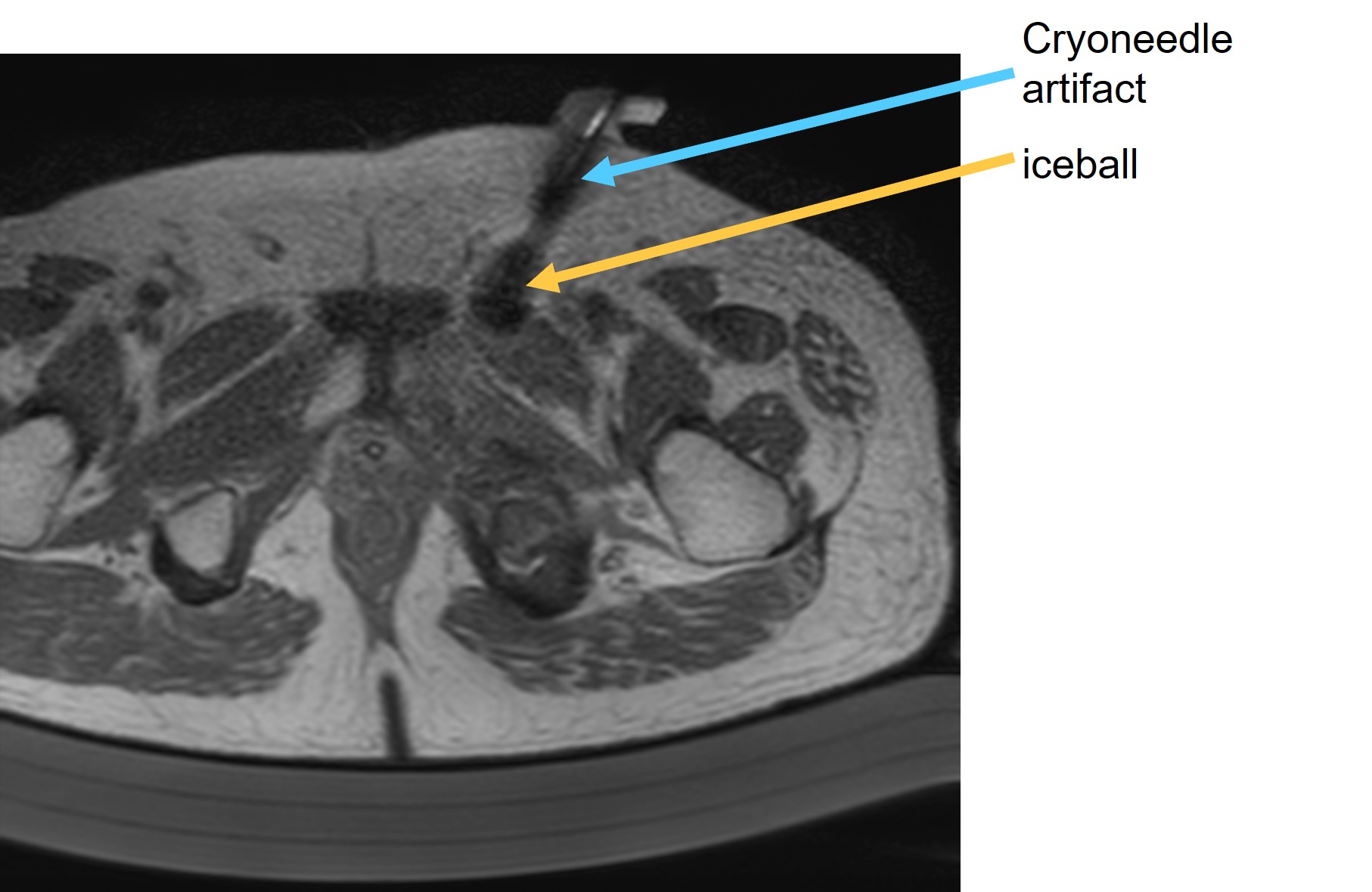
Example images showing the cryoneedle
artifacts during a cryoablation procedure. The artifacts introduced signal void
region much larger than typical metal artifacts from the cryoneedle and were similar in appearance to the iceball formed.
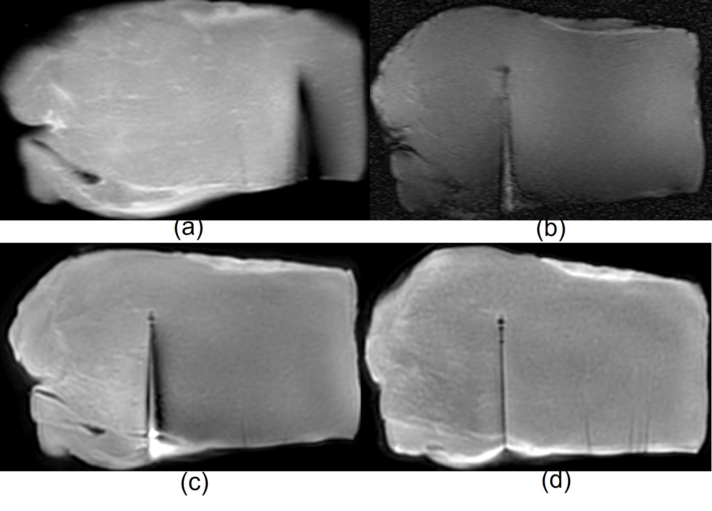
Coronal images demonstrate the cryoneedle artifacts in different tissue sample
experiments. (a) PD weighted image (b) T2-weighted image (c) UTE image acquired
with the tissue sampled placed ~3mm away from the patient table. Severe artifacts
are seen. d) UTE image acquired with the tissue sampled placed ~7mm away from the
patient table shown little cryoneedle artifacts.
DOI: https://doi.org/10.58530/2023/0727