0633
Application of Direct Signal Control with Variable Excitation and Refocusing for T2-w TSE Musculoskeletal Imaging at 7 Tesla1Erwin L Hahn Institute for MRI, University Duisburg-Essen, Essen, Germany, 2Medical Imaging, Radboud UMC, Nijmegen, Netherlands, 3High-Field and Hybrid MR Imaging, University Hospital Essen, Essen, Germany, 4Tesla Dynamic Coils, Zaltbommel, Netherlands, 5Physikalisch-Technische Bundesanstalt (PTB), Braunschweig und Berlin, Germany, 6Department of Diagnostic and Interventional Radiology and Neuroradiology, University Hospital Essen, Essen, Germany
Synopsis
Keywords: Joints, RF Pulse Design & Fields, UHF
First experiences with direct signal control with variable excitation and refocusing (DiSCoVER) for T2-weighted TSE imaging in 7 Tesla musculoskeletal (MSK) applications of hip, shoulder, and ankle are presented. Images were compared to static RF shimming aiming at a homogeneous excitation by using the MR system’s framework as well as optimizing for a B1+-efficient shim in an offline calculation. DiSCoVER yielded satisfying results within the ROI defined for signal optimization but showed more pronounced signal dropouts outside the ROI compared to static RF shimming. Workflow improvements were particularly noted for DiSCoVER as it calculates pTx scale factors under SAR constraints.Introduction
Turbo-spin echo (TSE) sequences are a challenge at ultra-high fields (UHF) as they rely on large flip angles (FA), and hence are not only prone to B1+ inhomogeneities, but also suffer from local specific absorption rate limitations. Body and musculoskeletal (MSK) imaging applications at 7T are known to be heavily impaired by radiofrequency (RF) inhomogeneities and enhanced tissue absorption, leading to strong FA variations and limited penetration depth, especially in large cross-sections.1 Recently, direct signal control with variable excitation and refocusing (DiSCoVER) has demonstrated improvements in image quality compared to static RF shimming for TSE brain imaging on 7T parallel transmission (pTx) MR systems.2-4 In this study, we report on first experiences in using the DiSCoVER technique outside of the brain for MSK imaging cases of the hip, ankle, and shoulder at 7T.Methods
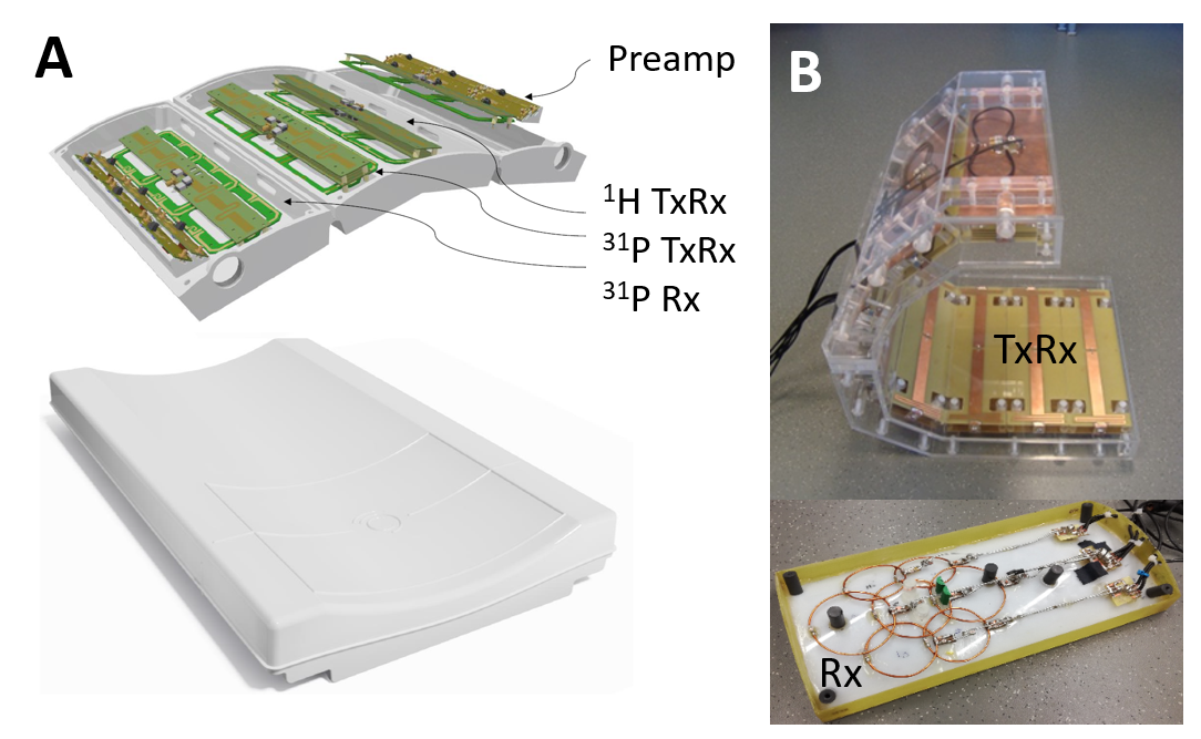
Imaging was performed on a 7T pTx system (Magnetom Terra, Siemens Healthcare, Germany) using an 8-channel body array (Tesla Dynamic Coils, The Netherlands) for hip imaging (Fig. 1A) and an 8-channel coil with an additional 7-channel receive array for ankle and shoulder imaging (Fig. 1B).5 For hip imaging one male, and for ankle/shoulder imaging two female subjects were included after obtaining informed consent. Specifications of the T2-weighted TSE sequence were as follows: TR=4500ms, TE=30ms, nominal FA=180°, TF=5, BW=200Hz/px. Spatial resolution/acquisition time varied between 0.4x0.4x3mm3 / 4:30min (ankle/shoulder) and 1x1x3mm3 / 2:40min (hip), respectively. For ankle imaging an additional set of T2-w TSE was acquired with SPAIR fat saturation. After acquiring images with the DiSCoVER optimization method two more datasets were generated with static RF shimming for comparison. First, the MR system’s integrated RF shimming algorithm was used which adjusts both amplitudes and phases of the RF coil automatically for a homogeneous excitation within a region of interest (ROI). Second, a phase-only optimization for a B1+-efficient excitation within the ROI was performed offline in MATLAB R2020a (MathWorks, MA) based on exported relative B1+ maps.6,7 The phase settings with equal amplitudes were then manually updated on the scanner console. ROIs were placed over the joints to be imaged and kept identical within one examination. Hip imaging started with unilateral optimization of the right joint only and followed by the optimization for both joints. Images were evaluated qualitatively regarding artifacts and homogeneity over the full cross section. For a quantitative evaluation contrast ratios (CR) were calculated between cartilage and bone, as well as between bone and Achilles tendon in the ankle.Results
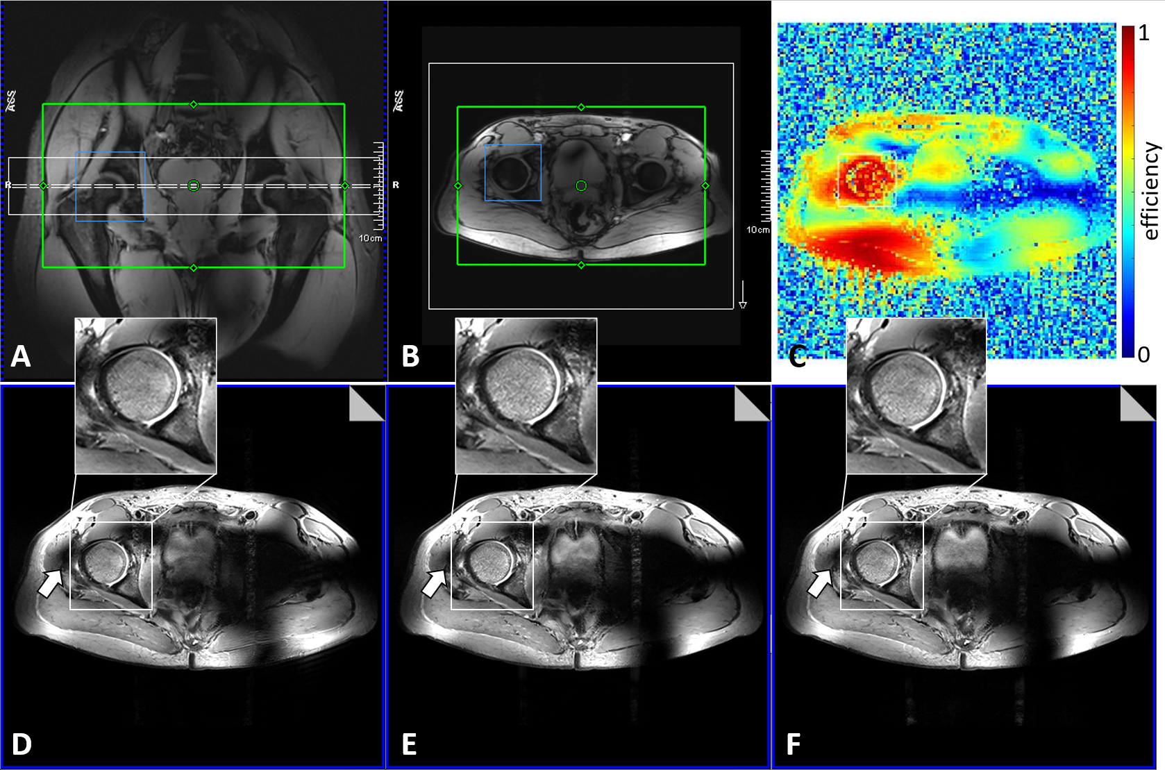
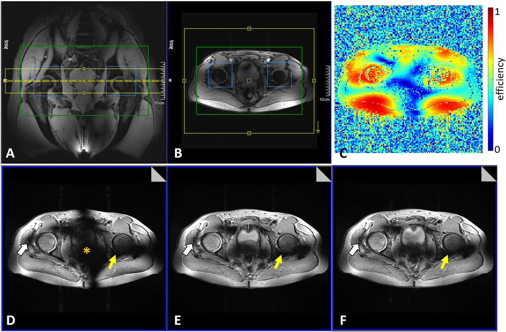
Unilateral imaging over the right hip joint yielded comparable results for all acquisitions with a good excitation over the ROI but a strong signal dropout at the contralateral joint (Fig. 2). An inhomogeneity at the gluteal muscle adjacent to the right femoral head was more pronounced with DiSCoVER compared to static RF shimming. On the other hand, DiSCoVER showed a 10% higher CR between femoral cartilage/bone and allowed 18 slices to be acquired within SAR guidelines compared to static RF shimming with 15 (homogeneous shim) and 14 slices (B1+-efficient shim), respectively.Bilateral hip imaging (Fig. 3) showed a similar excitation at the right joint but inferior quality at the left joint for all three scans. Notably, static RF shimming outperformed DiSCoVER at the left joint due to better delineation of the posterior part of the femoral cartilage. In addition, the central signal dropout is much less pronounced. CR measured for both hip joints was 10% better for DiSCoVER and B1+-efficient shim compared the homogenous shim. Time-averaged RF power varied between 19 and 22W for the hip exams.
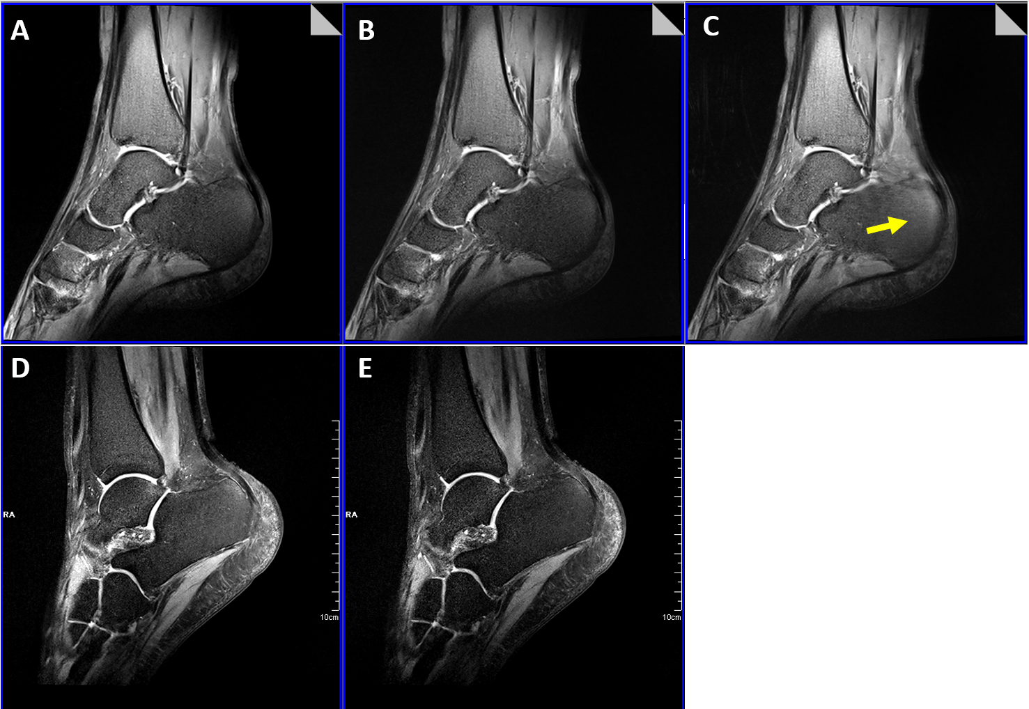
For imaging smaller joints homogeneous image quality without signal dropouts was obtained in the ankle with all three techniques (Fig. 4). However, some blurring was visible in the calcaneus for the B1+-efficient shim. CR between cartilage/bone was 12-16% better for DiSCoVER and the B1+-efficient shim compared to the homogeneous shim. A similar tendency was observed for CR between bone/tendon as well for the acquisitions with SPAIR fat saturation. Here, the SPAIR images obtained with DiSCoVER appeared sharper and less noisy compared to static RF shimming. Time-averaged RF power was 3.4W and yielded no limitations in spatial coverage.
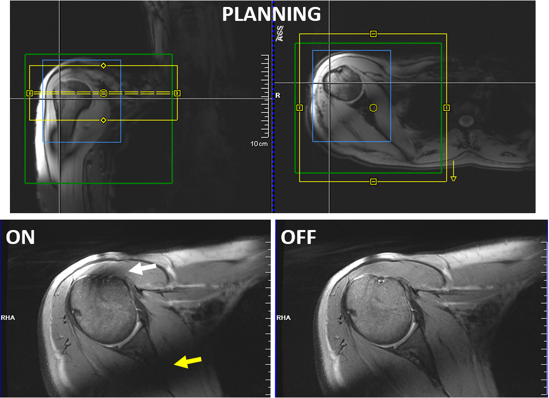
MR imaging of the shoulder joint (Fig. 5) yielded again stronger signal loss adjacent to the joint for DiSCoVER, both ventrally in the deltoid muscle and dorsal in the infraspinatus muscle and scapula. CR between cartilage/bone as well as between cartilage/fluid were similar for acquisitions with DiSCoVER and static RF shimming. Time-averaged RF power was 11.7W and yielded no limitations in spatial coverage.
Discussion and Conclusion
Overall, the DiSCoVER signal optimization technique for TSE imaging is very well integrated in the MR system and yields satisfying image quality in first applications outside the brain. Workflow improvements were particularly noted for hip imaging as DiSCoVER calculates pTx scale factors for excitation and refocusing pulses under SAR constraints. For static RF shimming, the MR system’s lookahead SAR prediction demanded a notable decrease in spatial coverage. Limitations with DiSCoVER were observed in regions adjacent to the ROI. Future work will focus on protocol optimization w.r.t. chemical shift artefacts and other TSE-variants like PD fat saturation and STIR, as well as on reproducibility in more subjects with varying body mass index.Acknowledgements
The body array coil used in this work was constructed with support from the European Fund for Regional Development EFRO OP-2014-2023-Oost [PROJ-01009].
Turbo spin-echo imaging with DiSCoVER signal homogenization was kindly provided by Siemens Healthineers as a work-in-progress sequence.
References
1. Kraff O, Quick HH. 7T: Physics, safety, and potential clinical applications. JMRI 2017;46(6):1573-1589.
2. Beqiri A, et al. Whole-brain 3D FLAIR at 7T using direct signal control. MRM 2018;80(4):1533-1545.
3. Malik SJ, et al. Direct signal control of the steady-state response of 3D-FSE sequences. MRM 2015;73(3):951-963.
4. Tomi-Tricot R, et al.
Fully integrated scanner implamentation of direct signal control for 2D
T2-weighted TSE at ultra-high fields. Proc. 29th Annual
Meeting ISMRM 2021; 621.
5. Rietsch SHG, et al. An 8-channel transceiver 7-channel receive RF coil setup for high SNR ultrahigh-field MRI of the shoulder at 7T. Med Phys 2017;44(12):6195-6208.
6. Van de Moortele P, et al.
Very fast multi channel B1 calibration at high field in the small flip angle
regime. Proc. 17th Annual Meeting ISMRM 2009; 367.
7. Schmitter S, et al. Cerebral TOF angiography at 7T: Impact of B1+ shimming with a 16-channel transceiver array. MRM 2014;71(3):966-977.
Figures