0611
7 Tesla MRI of the knee joint after anterior cruciate ligament graft reconstruction: safety discussion and image quality study1Erwin L Hahn Institute for MRI, University Duisburg-Essen, Essen, Germany, 2Department of Diagnostic and Interventional Radiology and Neuroradiology, University Hospital Essen, Essen, Germany, 3General Psychology: Cognition and Center for Behavioral Addiction Research (CeBAR), University Duisburg-Essen, Duisburg, Germany, 4High-Field and Hybrid MR Imaging, University Hospital Essen, Essen, Germany
Synopsis
Keywords: Safety, Artifacts
This study presents the MR safety discussion for imaging subjects with metallic fixation buttons after reconstruction of the anterior cruciate ligament, which have not been labeled MR conditional at 7T by the implant vendor. In addition, image quality and artifacts are evaluated in a knee imaging protocol consisting of both gradient- and spin echo sequences. Two imaging cases are presented: one with 7T imaging before and after surgery, and another case with comparative imaging between 1.5T and 7T. Artifact sizes from metallic fixation buttons at the femur did not impair the image quality and diagnostic evaluation of the knee joint.Introduction
Injuries of the anterior cruciate ligament (ACL) are very common among athletes, and MRI has been shown to be the imaging modality of choice.1 Although the evaluation of an ACL graft per se may not be an indication for an ultrahigh-field (UHF) examination of the knee joint, patients may very well be imaged at a clinically approved 7T MRI system during their course of life for assessing degeneration of cartilage or disease activity in rheumatic disorders, for example.2,3 Unfortunately, like other kinds of implants metallic suture buttons for ACL graft fixation at the femur have not been labeled MR safe or MR conditional for 7T by the implant manufacturers yet. On the other hand, implant safety and how to ensure access to UHF imaging are intensively discussed topics within the scientific community.4,5 In this study, we will report on our decision strategy for including subjects with metallic suture buttons without 7T labeling and on the presence of artifacts.Methods
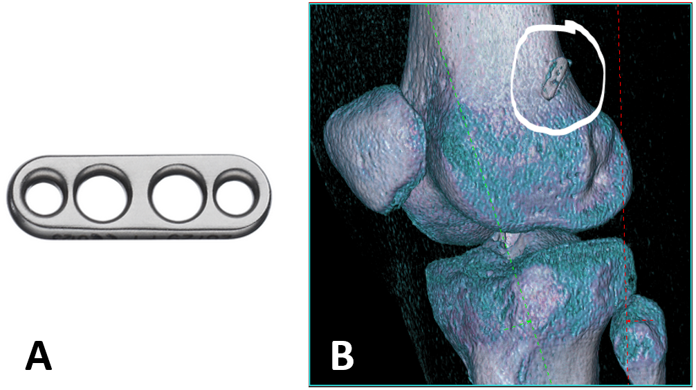
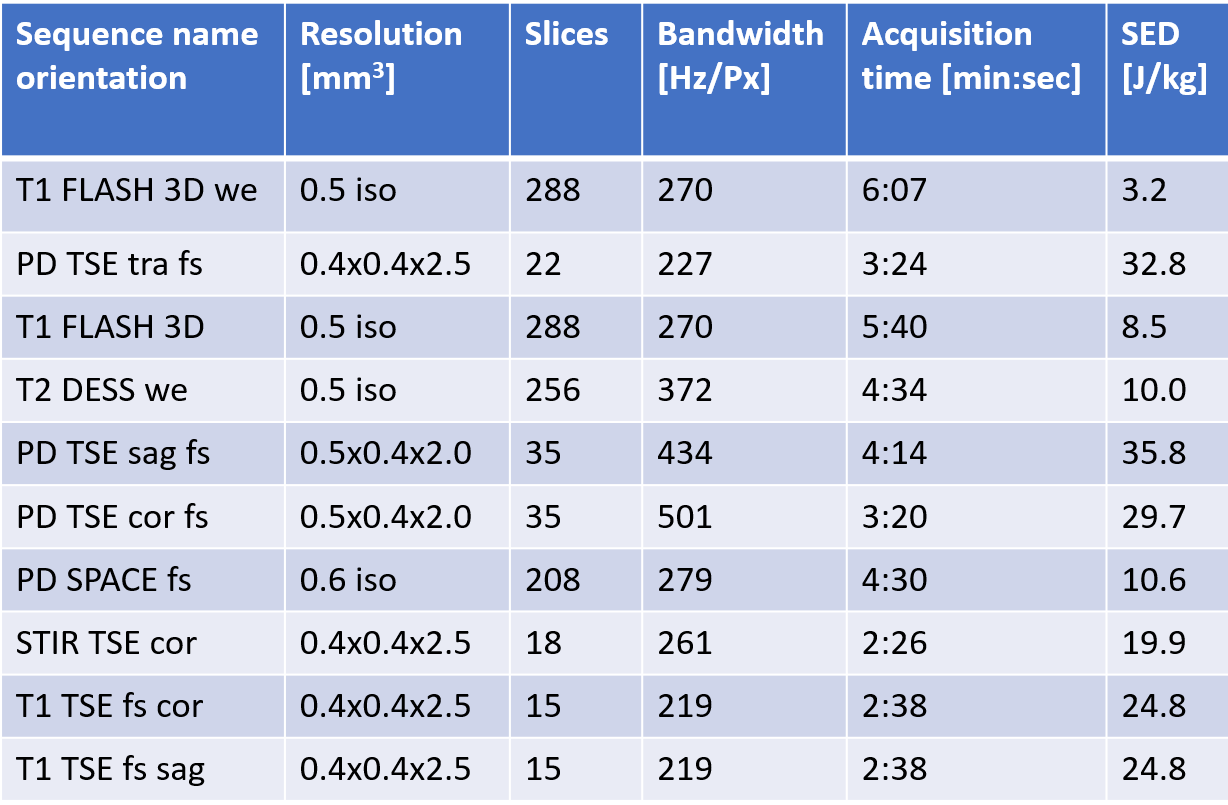
Two female subjects (ages 21/24 years, both soccer athletes) were included after obtaining informed consent. Our institutional MR safety board cleared the application of 7T MRI (MAGNETOM Terra, Siemens Healthcare, Germany) with metallic suture buttons within the direct radiofrequency (RF) exposure volume of the clinically approved 1-channel transmit/28-channel receive knee coil (Quality Electrodynamics, OH) based on literature research. One subject was imaged at 7T right before as well as 6 weeks after ACL graft reconstruction in her right knee. In this case a titanium FLIPPTACK fixation button (Karl Storz, Germany) of length 12mm and width 4mm was implanted (Fig. 1A). The other subject was imaged only after surgery of her left knee at 7T but could also provide comparative 1.5T MR images (MAGNETOM Sola, Siemens). In her case, the exact model of the fixation button was unknown, but it was verified to be made of titanium and the subject could provide CT images which yielded similar dimensions of the implant (length 14mm, width 4mm) (Fig. 1B). Additionally, biodegradable interference screws made of non-metallic polylactides were implanted in both subjects (length 20-30mm). The MRI protocol at 7T consisted of both gradient (3D-FLASH and DESS) and spin echo sequences (2D-TSE with fat saturation, 3D-SPACE) as provided in Fig. 2, as well as flip angle (FA) mapping using the 3DREAM technique.6 Extent of metal-induced artifacts were measured on the scanner’s console (syngo, VE12U) in slices showing greatest distortions. Additionally, a radiologist experienced in musculoskeletal imaging at 7T performed a qualitative evaluation regarding delineation of anatomical structures and potential diagnostic impairment by artifacts adjacent to the implant.Results
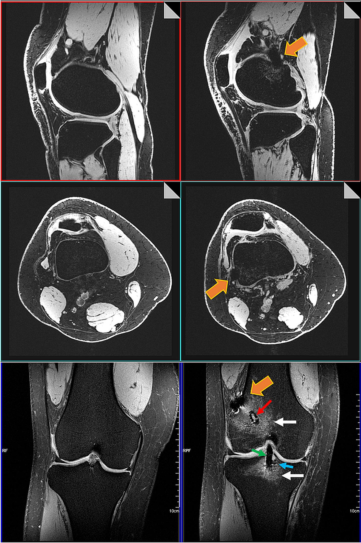
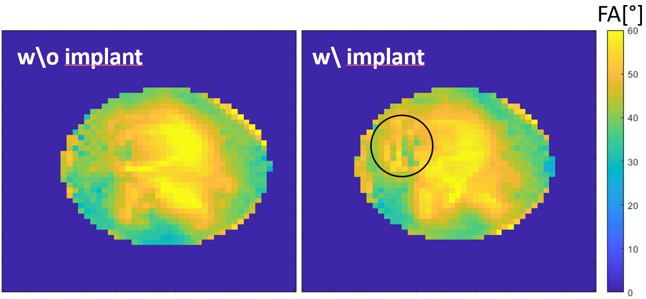
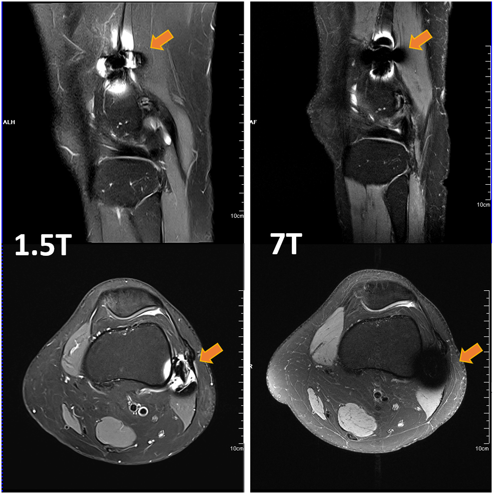
The rationale for clearing the fixation buttons for 7T MRI was built up on results from extensive safety assessments on cranial fixation plates, which showed no heating.7-11 Both implant types are of similar dimension and shape and were studied using a circular polarized B1+ excitation in single channel mode. In addition, the length of the implant is much smaller than the resonance length of around 4-5cm at 7T, where other implant studies showed a small increase in temperature of 1-3°C.7,8,12,13 However, numerical studies also showed that a parallel E-field polarization could lead to 50% increase in 1-g-averaged SAR and 10% increase in 10-g-averaged SAR compared to the case without any implants present.9 Hence, 7T MRI was restricted to normal mode exposure levels.14Both subjects were imaged without complications at 7T within an examination time of approximately 45 minutes and a specific energy dose of 210J/kg. No sensations of heat or discomfort were reported by the subjects. Images were only minimally compromised by metal-induced artifacts (signal pile-up, nulling, geometric distortions) within the direct vicinity of the implants. Artifact sizes were measured to 18mm x 11mm for the FLIPPTACK implant (Fig. 3). Similar, the FA maps (Fig. 4) showed only slight influence of the FLIPPTACK implant on the overall B1 distribution (45.1°±8.0° without vs. 45.9°±7.3° with implant) as well as within a small ROI at the implant location (44.5°±3.6° without vs. 48.8°±4.9° with implant). For the comparison between 7T and 1.5T MRI similar artifact sizes of up to 31mm x 30mm were measured for the other implant at both field strength as shown in Fig. 5.
Discussion and Conclusion
It can be expected that the number of 7T MRI systems for clinical use will increase in the future. On the other hand, almost no medical implant has been labeled MR conditional for 7T, so far, and most implants probably will never be tested for this field strength. While each and every case of an implant must always be thoroughly discussed at 7T, for small metallic but non-magnetic implants with dimensions much smaller than the resonance length at 7T and of similar geometry to those implants that have already been assessed in the published literature, access to 7T may be granted by comparing the exposure scenarios and by transferring the results. In addition, 7T MRI also performs very well in the low RF power range with optimized imaging protocols. Artifact sizes from fixation buttons at the femur were similar in shape and extent compared between 1.5T and 7T and did not interfere with the general delineation of anatomical and pathological structures of the knee joint.Acknowledgements
No acknowledgement found.References
1. Pujol N, Blanchi MP, Chambat P. The incidence of anterior cruciate ligament injuries among competitive Alpine skiers: a 25-year investigation. Am J Sports Med. 2007;35(7):1070-1074.
2. Treutlein C, et al. Comprehensive assessment of knee joint synovitis at 7 T MRI using contrast-enhanced and non-enhanced sequences. BMC Musculoskelet Disord. 2020;21(1):116.
3. Trattnig S, et al. [Biochemical cartilage imaging-update 2019]. Der Radiologe. 2019;59(8):742-749.
4. Kraff O, Quick HH. 7T: Physics, safety, and potential clinical applications. JMRI 2017;46(6):1573-1589.
5. German Ultrahigh Field Imaging Network (GUFI). Approval of subjects for measurements at
ultra-high-field MRI. 2015; https://mr-gufi.de/index.php/en/documents.
6. Ehses P, et al. Whole-brain B1 -mapping using three-dimensional DREAM. MRM 2019;82(3):924-934.
7. Noureddine Y, et al. Radiofrequency induced heating around aneurysm clips using a generic birdcage head coil at 7 Tesla under consideration of the minimum distance to decouple multiple aneurysm clips. MRM 2019;82(5):1859-1875.
8. Noureddine Y, et al. In vitro and in silico assessment of RF-induced heating around intracranial aneurysm clips at 7 Tesla. MRM 2018;79(1):568-581.
9. Kraff O, et al. MR safety assessment of potential RF heating from cranial fixation plates at 7 T. Med Phys 2013;40(4):042302.
10. Sammet CL, et al. RF-related heating assessment of extracranial neurosurgical implants at 7T. MRI 2013;31(6):1029-1034.
11. Chen B, et al. Cranial fixation plates in cerebral magnetic resonance imaging: a 3 and 7
Tesla in vivo image quality study. MAGMA. 2016;29(3):389-98.
12. Oriso K, et al. Impact of the Static and Radiofrequency Magnetic Fields Produced by a 7T MR Imager on Metallic Dental Materials. MRMS 2016;15(1):26-33.
13. Wezel J, Kooij BJ, Webb AG. Assessing the MR compatibility of dental retainer wires at 7 Tesla. MRM 2014;72(4):1191-1198.
14. International Electrotechnical Commission (IEC). 60601-2-33 Medical electrical equipment – Part 2-33: Particular requirements for the basic safety and essential performance of magnetic resonance equipment for medical diagnosis. Edition 3.2; 2015.
Figures