0609
RF coil safety validation with a 3D SAR measurement setup
Nur Izzati Huda Zulkarnain1, Mert Ates2, Grace Cole3, Alireza Sadeghi-Tarakameh1, Steve Jungst1, Lance DelaBarre1, Gregor Adriany1, and Yigitcan Eryaman1
1Center for Magnetic Resonance Research (CMRR), University of Minnesota, Minneapolis, MN, United States, 2Department of Electrical and Electronics Engineering, Bilkent University, Ankara, Turkey, 3Bethel University, St Paul, MN, United States
1Center for Magnetic Resonance Research (CMRR), University of Minnesota, Minneapolis, MN, United States, 2Department of Electrical and Electronics Engineering, Bilkent University, Ankara, Turkey, 3Bethel University, St Paul, MN, United States
Synopsis
Keywords: Safety, Validation
We implemented a framework to validate the RF safety of MRI coils experimentally using a phantom in our RF safety lab which supports coil excitation using up to 16 individually-controlled power amplifiers. A 3D measurement setup and a dosimetric probe were used to map the spatial distribution of the specific absorption rate (SAR). To demonstrate the accuracy of the framework, we compared the simulated and measured 10 g averaged SAR of a rectangular loop element and an 8-channel transmit/receive head coil. We obtained quantitative agreements with 7.8% and 11.6% root-mean-squared error for the loop element and head coil respectively.Introduction
Ultra-high field (UHF) magnetic resonance imaging (MRI) has advantages such as increased signal-to-noise ratio (SNR), sensitivity, spatial and spectral resolution1-2. However, the higher operating frequency poses a risk of higher power dissipation in tissue3. Specific absorption rate (SAR) is the quantity used to evaluate the power dissipation in a volume of interest. Peak 10 g SAR is constrained by the safety guidelines in order to ensure patient safety. Electromagnetic (EM) simulation is typically used to calculate the 10 g SAR generated in a phantom model4 mimicking the dielectric and thermal properties of the tissue of interest4. Experimental validation of the calculated SAR distribution is of paramount importance.Recognizing the need for a robust multipurpose 3D measurement system, Han et al. introduced COSI Measure, an automated open-source system suitable for coil characterization and evaluation purposes5. In this work, we utilized a similar 3D measurement system to measure the 10 g SAR distribution of a simple loop element and an 8-channel transmit/receive head coil6 at 447 MHz and compared it against the simulated distribution. Unlike an MR-based validation, this framework maps the SAR using a near-field dosimetric probe in a controlled RF safety lab environment. Figure 1 shows the equipment used in the validation studies in the safety lab. Phantoms containing viscous gel with specific dielectric and thermal properties were exposed to RF fields generated by the coils. The coils were excited by individual amplifiers where the magnitude and phase of each channel could be separately controlled. A comparison is made between the simulation and experimental data, and the error is quantified.
Method
The RF coil validation framework uses a 3D measurement system equipped with 3 orthogonal axes with a working volume of 500×500 ×700 mm in a controlled safety lab environment. The system can move a field probe in 3D motion with submillimeter accuracy. In this validation, a high-precision, isotropic E-field/dosimetric probe (EX3DV4, SPEAG, Zurich, Switzerland) was used to map the SAR distribution in the phantom. The validation was performed with a polyvinylpyrrolidone (PVP) phantom7 (598 g/L PVP, 22.31 g/L NaCl, 0.475 g/L NiCl2 6H2O and 8.1 g/L agar) with conductivity and permittivity of 0.90 S/m and 52. The thermal conductivity and specific heat capacity of the phantom were 0.41 W/m-K and 3.66 MJ/m3-K respectively.We demonstrated the use of the framework with validations of the electromagnetic model of two RF coils: a 145 x 60 mm rectangular loop element and an 8-channel transmit/receive head coil. The loop element was validated with a rectangular phantom while the head coil was validated with a cylindrical phantom. Figure 2 shows the coils and phantoms that were set up within the 3D measurement system. A set of individual RF power amplifiers supplied 25 W to the loop element and 17 W (total) to the head coil at 447 MHz. The path of the field probe was programmed in motion control software (Mach3, Newfangled Solutions, Maine, USA). The SAR measurements were performed at 3 depths and covered the cross-sectional area of the box and cylindrical phantoms. The 10 g averaged SAR measurements were compared against the SAR distribution of both coils simulated in an EM analysis software (CST Studio Suite, Darmstadt, Germany). Figure 3 shows the modeled coil and phantom setup in the simulation to replicate the conditions of the experimental validation.
Results
Fig. 4 shows the comparison between the simulated SAR and the measured SAR distribution of the loop element and the 8-channel transmit/receive head coil array. The loop element showed a good agreement with 7.8% RMSE while the bumped dipole showed an agreement with 11.6% RMSE.Discussion
The here-described RF coil validation framework can be broadly used to assess the safety of all types of RF coils - including transmit coils with receiver array inserts. In the future, this framework will be extended for validations with different excitation patterns and RF coils. It can also support the validation of larger coils such as body arrays that requires the use of a bigger phantom.In addition to RF coil safety validation, the submillimeter resolution of the 3D setup also allows safety assessment of small passive conductive medical implants such as deep brain stimulation electrodes and coronary stents8.
Conclusion
We successfully built a 3D measurement setup and fully validated the safety of two RF coils using the calibrated setup in our RF safety lab. This setup and the associated SAR measurements achieved high agreement between simulation and experiment with 7.8% RMSE for the loop dipole element and an excellent 11.6% RMSE for the more complex bumped dipole array.Acknowledgements
This work was supported by NIBIB P41 EB027061, NINDS R01NS115180 and a University of Minnesota Medical School/UMF Equipment Grant.References
- Ugurbil K. Magnetic resonance imaging at ultrahigh fields. IEEE Trans Biomed Eng. 2014 May;61(5):1364-79. doi: 10.1109/TBME.2014.2313619. Epub 2014 Mar 25. PMID: 24686229; PMCID: PMC4135536.
- Vachha, B., Huang, S.Y. MRI with ultrahigh field strength and high-performance gradients: challenges and opportunities for clinical neuroimaging at 7 T and beyond. Eur Radiol Exp 5, 35 (2021). https://doi.org/10.1186/s41747-021-00216-2
- van Osch, M.J.P., Webb, A.G. Safety of Ultra-High Field MRI: What are the Specific Risks?. Curr Radiol Rep 2, 61 (2014). https://doi.org/10.1007/s40134-014-0061-0
- Hoffmann, J., Henning, A., Giapitzakis, I. A., Scheffler, K., Shajan, G., Pohmann, R., and Avdievich, N. I. (2016) Safety testing and operational procedures for self-developed radiofrequency coils. NMR Biomed., 29: 1131– 1144. doi: 10.1002/nbm.3290.
- Han, H., Moritz, R., Oberacker, E. et al. Open Source 3D Multipurpose Measurement System with Submillimetre Fidelity and First Application in Magnetic Resonance. Sci Rep 7, 13452 (2017). https://doi.org/10.1038/s41598-017-13824-z
- Sadeghi-Tarakameh A, DelaBarre L, Lagore RL, Torrado-Carvajal A, Wu X, Grant A, Adriany G, Metzger GJ, Van de Moortele PF, Ugurbil K, Atalar E, Eryaman Y. In vivo human head MRI at 10.5T: A radiofrequency safety study and preliminary imaging results. Magn Reson Med. 2020 Jul;84(1):484-496. doi: 10.1002/mrm.28093. Epub 2019 Nov 21. PMID: 31751499; PMCID: PMC7695227.
- Duan, Q., Duyn, J.H., Gudino, N., de Zwart, J.A., van Gelderen, P., Sodickson, D.K. and Brown, R. (2014), Characterization of a dielectric phantom for high-field magnetic resonance imaging applications. Med. Phys., 41: 102303. https://doi.org/10.1118/1.4895823
- Winter L, Oberacker E, Özerdem C, Ji Y, von Knobelsdorff-Brenkenhoff F, Weidemann G, Ittermann B, Seifert F, Niendorf T. On the RF heating of coronary stents at 7.0 Tesla MRI. Magn Reson Med. 2015 Oct;74(4):999-1010. doi: 10.1002/mrm.25483. Epub 2014 Oct 7. PMID: 25293952.
Figures
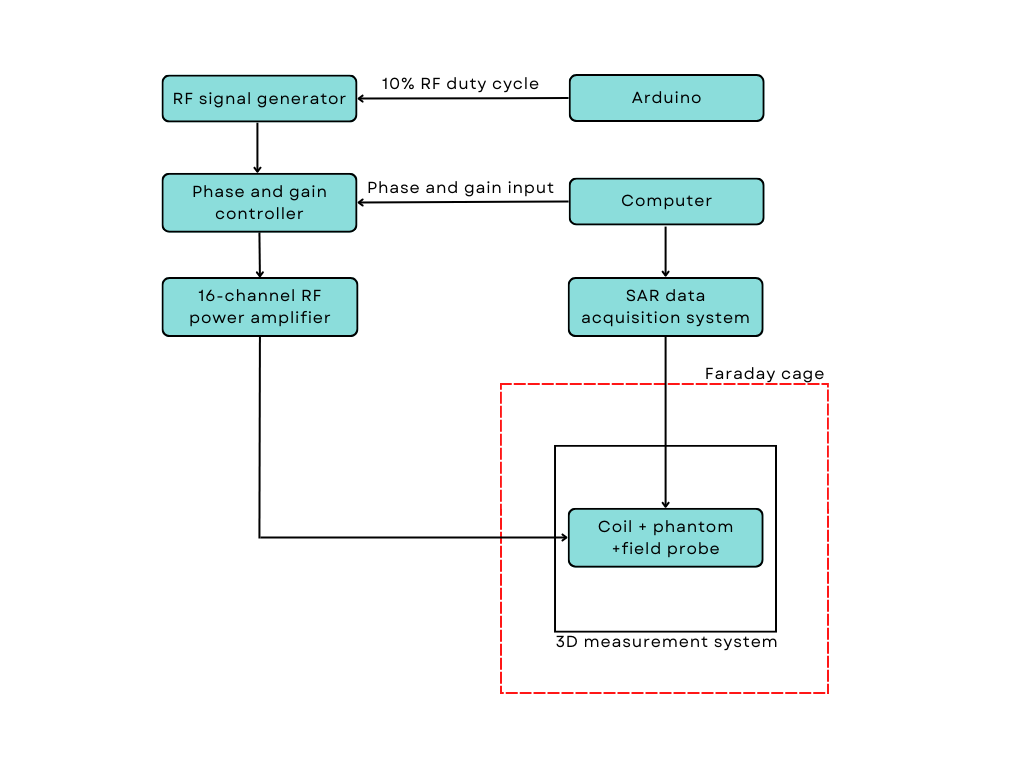
Figure 1. Block diagram of the equipment in the safety lab used in the RF coil safety validation framework.
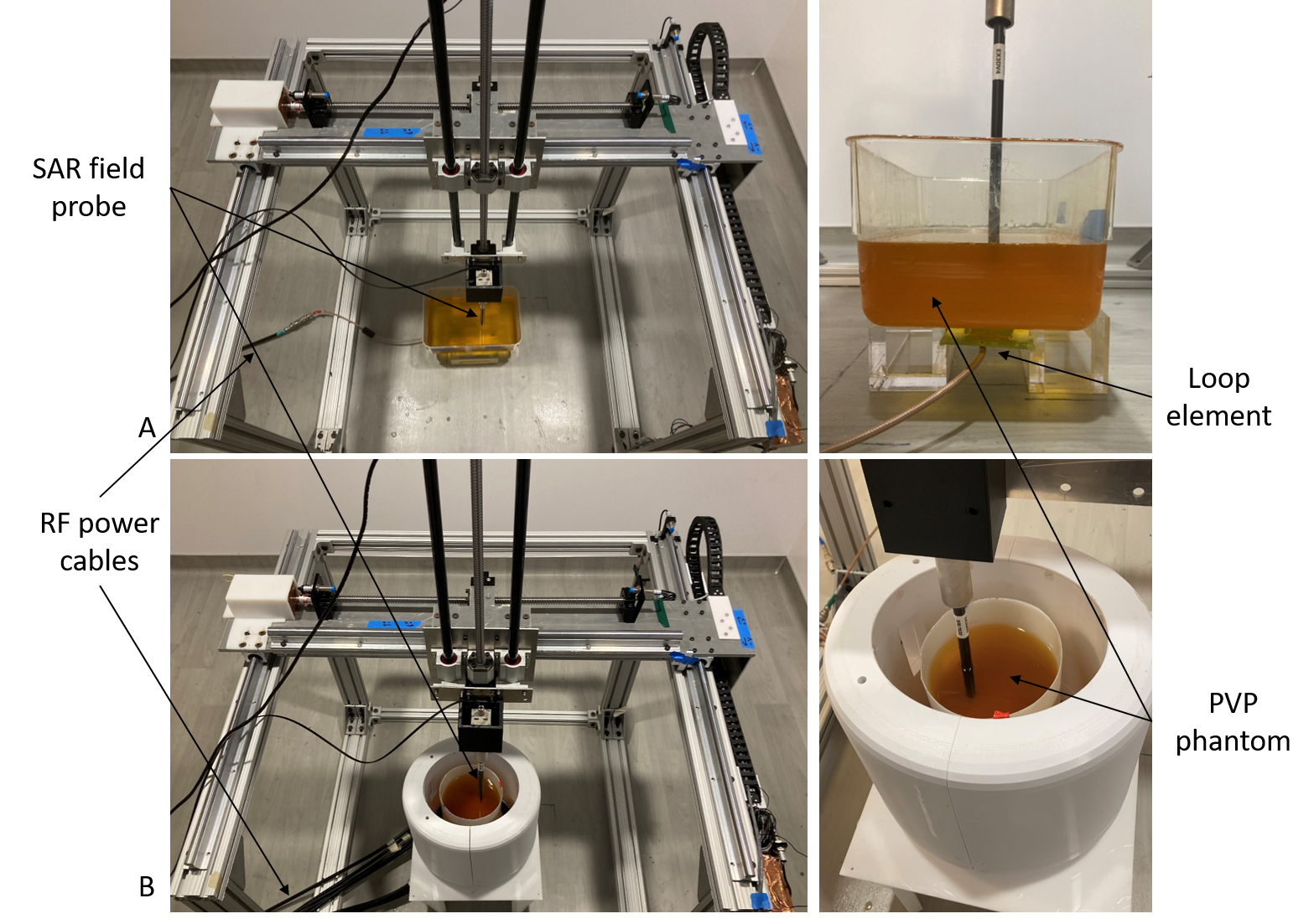
Figure 2. Experimental setup of the loop element with the box phantom (A) and head coil with the cylindrical phantom (B) positioned at the center of the 3D measurement setup in the Faraday cage.
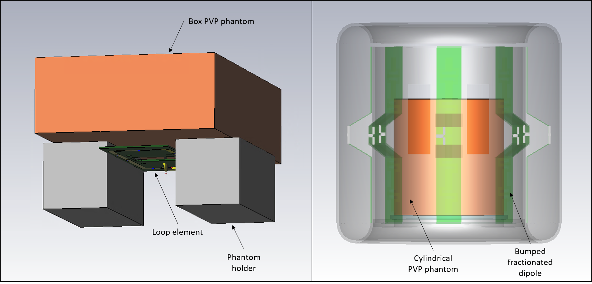
Figure 3. PVP phantoms and RF coils modeled in the EM simulation.
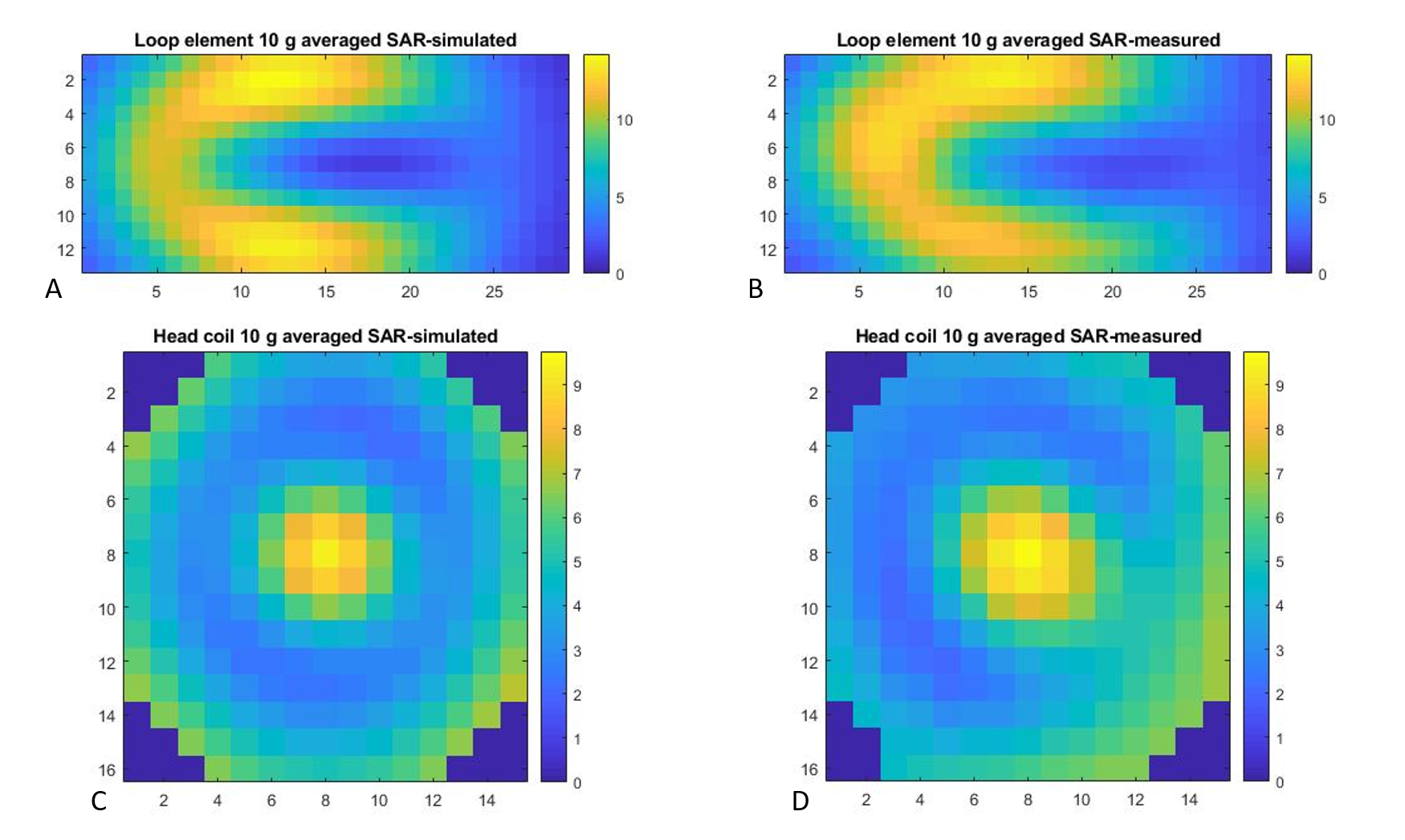
Figure 4. Simulated and measured 10 g averaged SAR distribution of the loop element (A-B) and 8-channel head coil (C-D)
DOI: https://doi.org/10.58530/2023/0609