0607
Assessment of MRI-related heating with excess deep brain stimulation extension wires at 3 tesla1Cleveland Clinic Foundation, CLEVELAND, OH, United States, 2University of Colorado Anschutz Medical Campus, Aurora, CO, United States, 3University of Colorado Denver, Denver, CO, United States
Synopsis
Keywords: Safety, Safety
When implanting a DBS system, the excess amount of extension wires is looped and placed in different regions (near the skull burr holes or in the chest), depending on the neurosurgeon/institution. In this study, we tested three different DBS configurations with excess extension wires looped behind the IPG. A phantom with a DBS device (lead model B33005, IPG Percept B35200, and Extension wire model B34000) was used to perform this study. We observed that the temperature rise was higher with one loop placed behind the IPG compared to two or no loops.
Introduction
Deep brain stimulation (DBS) devices consist of DBS leads with contacts connected to the implantable pulse generator (IPG) through an extension wire. After the placement of DBS leads to the target area of the brain, it exits the brain through the burr hole in the skull. The extension wire travels from the head, then down the side of the neck to the IPG, which is usually implanted subcutaneously below the clavicle. Typically, the excess DBS lead is looped under the scalp near the burr hole and under the IPG. It is estimated that approximately 70% of patients with DBS may require an MRI within 10 years of their implantation [1]. When performing MRI in patients with DBS, the heating of DBS devices is a major concern [2, 3]. Studies have reported that the geometry of the DBS device in the MRI can impact the temperature rise at the electrodes [4, 5]. Usually, the configuration of DBS varies across institutions in terms of electrode model type, vendors, placement of excess extension wires, and positioning of the IPG. Therefore, an improved knowledge of safety testing with different DBS configurations is necessary to ensure the safety of patients with DBS devices. In this study, we explored how the looping of excess extension wires behind the IPG could affect the temperature rise at the electrodes.Methods
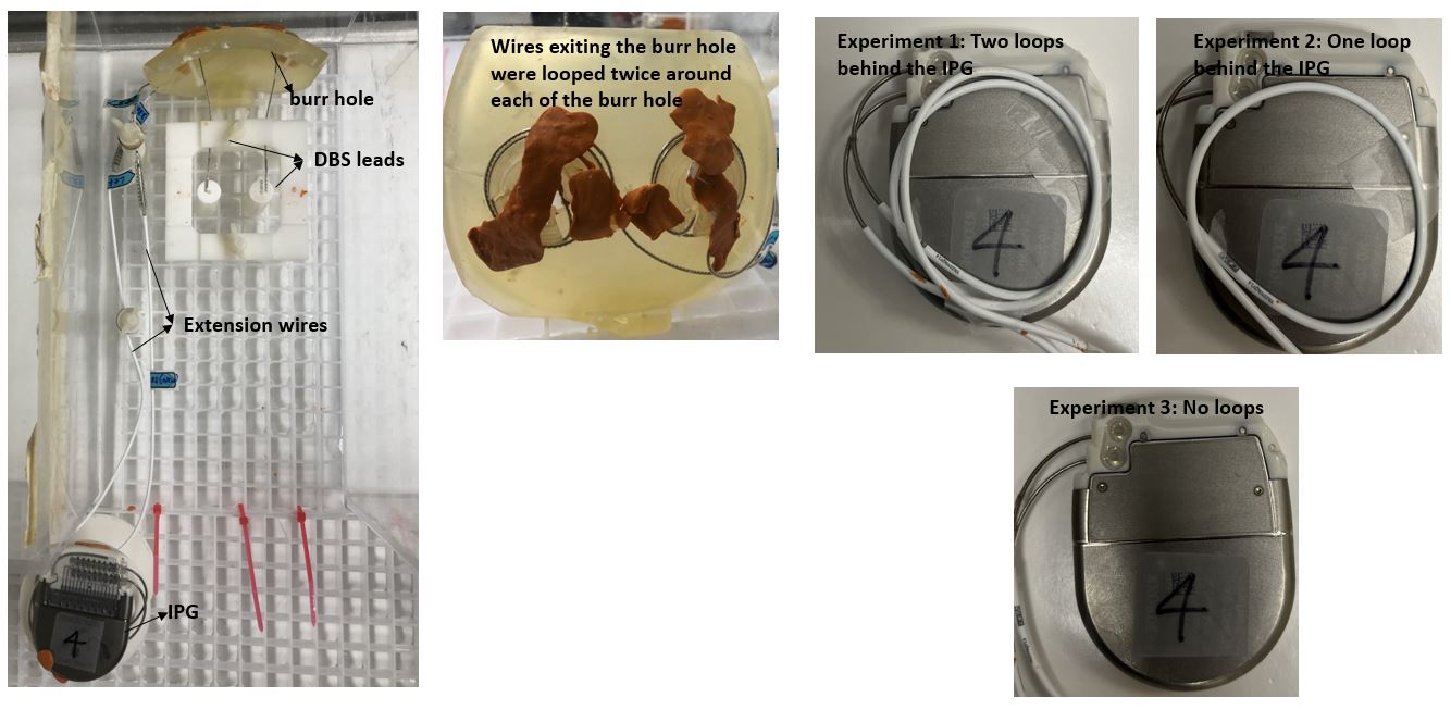
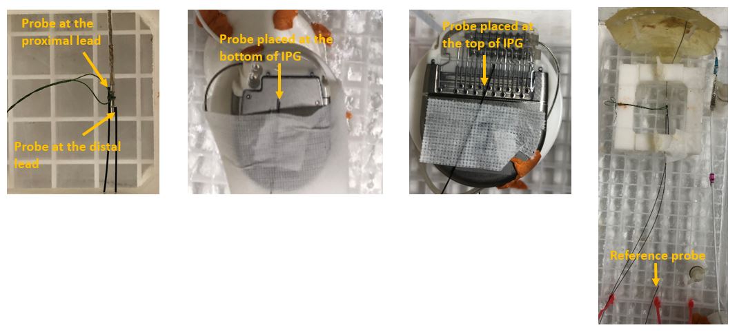
An anthromorphic ASTM phantom was filled up with polyacryclic gel (ASTM F2182 – 11a standard) having similar conductivity and dielectric constant as human tissue with a bilateral Medtronic DBS system was used. The DBS system included leads (Model B33005), extension wires (Sensight™ Extension model B34000) and an IPG (Percept, B35200). This study was performed at two centers: site 1 and site 2. Phantom was scanned on a 3 T Prisma (Siemens, Germany) and 3 T Skyra (Siemens, Germany) MRI scanner at site 1 and site 2 respectively, using a transmit-receive head coil. During the experiments, the IPG placed on the right side of the phantom was turned ON at bipolar settings (right side: active contacts were 8- and 10+; frequency 130 Hz, pulse width 60 msec, current 5mA; left side was turned off). Heating in different looping configurations behind the IPG during a T2 turbo spin echo (T2-TSE) (TR/TE = 6470 ms/71 ms; flip angle: 150o; slice thickness = 4 mm; matrix size = 256x256) was tested. The specific absorption rate of T2-TSE generating 14.9 W of time averaged RF power and B1+rms value of 2.3 µT were 0.2 W/kg, 2.8 W/kg, and 2.8 W/kg for whole body, exposed body and head respectively. The DBS leads were inserted through the burr holes in the phantom head. The excess wires exiting the burr hole were looped twice around each of the burr holes, and the rest of the wires were looped under the IPG in three different configurations: (1) Experiment 1: bilateral DBS with each excess extension wire looped twice under the IPG, i.e., one from the top channel (connecting to the left lead) and the other one from the bottom channel (connecting to the right lead); (2) Experiment 2: bilateral DBS with only the excess extension wire connecting to the left lead looped once under the IPG, while not looping the other extension wire; and (3) Experiment 3: bilateral DBS with no loops. Figure 1 shows the images of the phantom, position of the IPG, and experimental DBS configurations. The temperature probes were placed on distal and proximal leads (both left and right), top and under the IPG (Figure 2), and the temperature changes were measured using a fluoroptic temperature sensor (model m3300, Luxtron (Lumasense Technologies), Santa Clara, CA, USA).Results and Discussion
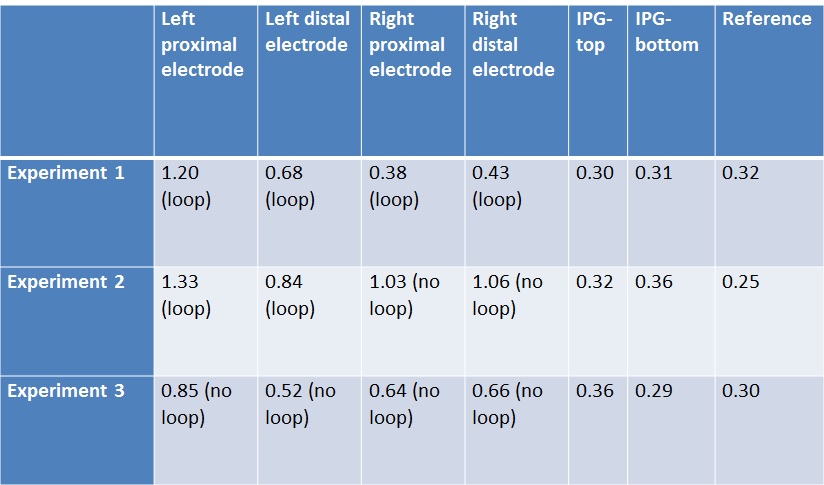
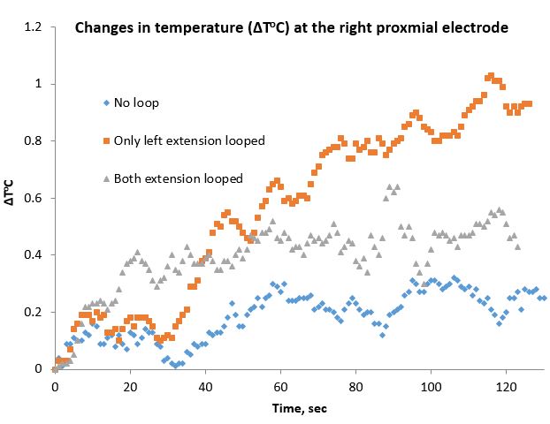
Table 1 shows the temperature rises from site 1 at the left and right proximal and distal electrodes, the IPG surfaces, and the reference electrode during a bipolar setting for DBS using a Percept IPG. It is evident from Table 1 that in the bilateral configuration when either one or both wires are looped, left / right extension wire looping causes less temperature rise in the corresponding electrodes. So, the temperature rise was higher with one loop placed under the IPG compared to two or no loops. For example, figure 3 shows the change in temperature over time at three different DBS configurations at the right proximal electrode. However, overall heating is less when no wire is looped. Interestingly, no temperature rise of the IPG was observed. We also replicated similar results at site 2.While effect of looping around IPG has been explored before [5], here we report the heating effect using a directional DBS lead, and Percept IPG validated at two sites. The heating condition will depend on the local B and E field in presence/absence of the loops [6]. However, it needs to be noted, that while the absolute temperature rise depends on the exact routing/configuration, the effect of looping will be observed in all conditions.
Conclusion
The temperature rise at the electrodes can vary depending on the DBS configuration. Different looping of extension wire around the IPG can cause different degrees of temperature rise.Acknowledgements
Center for Neurological Restoration at the Cleveland Clinic Foundation.References
1. Boutet, A., et al., Functional MRI Safety and Artifacts during Deep Brain Stimulation: Experience in 102 Patients. Radiology, 2019. 293(1): p. 174-183.
2. Rezai, A.R., et al., Is magnetic resonance imaging safe for patients with neurostimulation systems used for deep brain stimulation? Neurosurgery, 2005. 57(5): p. 1056-62; discussion 1056-62.
3. Rezai, A.R., et al., Neurostimulation system used for deep brain stimulation (DBS): MR safety issues and implications of failing to follow safety recommendations. Invest Radiol, 2004. 39(5): p. 300-3.
4. Rezai, A.R., et al., Neurostimulation systems for deep brain stimulation: in vitro evaluation of magnetic resonance imaging-related heating at 1.5 tesla. J Magn Reson Imaging, 2002. 15(3): p. 241-50.
5. Boutet, A., et al., 3-Tesla MRI of deep brain stimulation patients: safety assessment of coils and pulse sequences. J Neurosurg, 2019. 132(2): p. 586-594.
6. Panych, L.P. and B. Madore, The physics of MRI safety. J Magn Reson Imaging, 2018. 47(1): p. 28-43.
Figures