0605
Surgical modification of deep brain stimulation lead trajectories reduces RF heating during 3 T MRI: From phantoms to implementation in patients1Biomedical Engineering, Northwestern University, Evanston, IL, United States, 2Radiology, Northwestern University, Chicago, IL, United States, 3Neurosurgery, Northwestern University, Chicago, IL, United States
Synopsis
Keywords: Safety, Brain, Translational studies
MRI at 3 T is restricted for patients with deep brain stimulation (DBS) systems due to potential radiofrequency (RF) heating. Here, we present the first large-scale, systematic study to determine how trajectory-related parameters affect RF heating and quantify the extent of RF heating reduction. Introducing concentric loops close to the surgical burr hole substantially reduced RF heating. Increasing the number of loops correlated well with decreased heating. Recommendations based on the results from phantom experiments were easily adopted during the surgical procedure within 30 seconds. Subsequent replication of the trajectories based on postoperative computed tomography images confirmed low RF heating.Introduction
Approximately 70% of patients with deep brain stimulation (DBS) implants will require an MRI exam within 10 years following device implantation1. Radiofrequency (RF) tissue heating around the DBS lead-tip is a well-known safety risk, leading to strict imaging guidelines. The lead trajectory and its orientation with respect to the MRI electric fields contribute to variations in the magnitude of RF heating across patients2,3. Recent studies showed that incorporating concentric loops in the extracranial trajectory of the lead can reduce RF heating, but the optimal positioning of the loop remains unknown2,4-5. Here, we systematically evaluated the RF heating of 244 unique lead trajectories to elucidate the trajectory characteristics that minimize RF heating and presented the first surgical implementation of these trajectory specifications.Methods
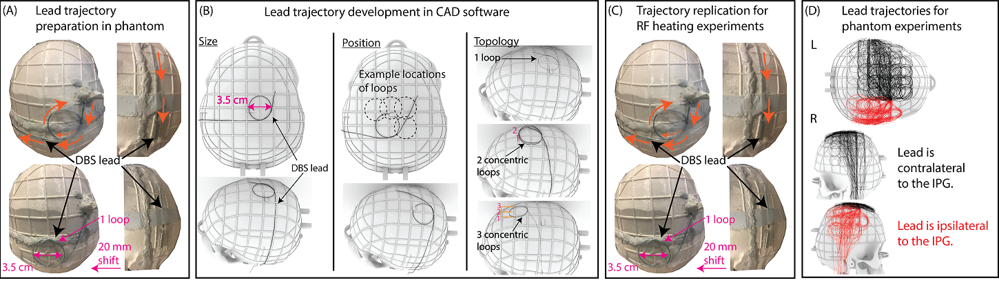
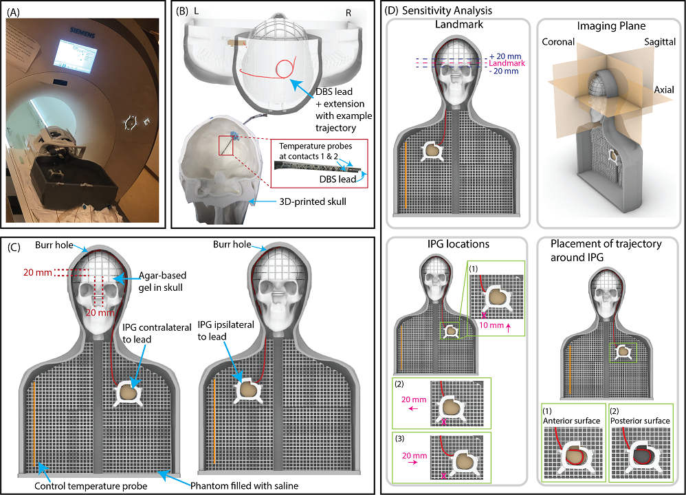
Lead trajectory optimization: We systematically examined the effect of three extracranial lead trajectory parameters on RF heating: the diameter of the concentric loops (2.5-4.5 cm), position of the loops on the skull that are surgically and anatomically feasible, and the number of concentric loops (1-3 loops) (Figure 1).Experimental setup: A total of 244 phantom measurements were performed to determine the DBS lead trajectories that minimized RF induced heating. Experiments were performed with an Abbott full DBS system (lead model 6172, extension model 6371, and Infinity-5 IPG) where the lead was implanted in the right side of the skull phantom (Figures 2A-C). The DBS system was implanted in an anthropomorphic phantom comprised of a brain tissue mimicking agar-based gel (σ=0.47 S/m, 𝜀r=78) that filled the skull and saline solution (σ=0.50 S/m, 𝜀r=80) mimicking the conductivity of average human tissue in the remainder of the phantom. The maximum temperature increase, ΔTmax, was measured at the lead-tip using fiber-optic temperature probes (Osensa, BC, Canada). Experiments were performed with a T1-weighted turbo spin echo dark fluid pulse sequence (acquisition time=381 seconds, B1+rms=2.7 µT) in a 3 T Prisma MRI scanner (Siemens Healthineers, Erlangen, Germany).
Test-retest analysis: To evaluate the reliability of our measurements, we repeated experiments for 18 randomly selected trajectories. These trajectories were selected from those that generated RF heating in the top and bottom 20% as well as those in between these thresholds. We calculated the Intraclass Correlation Coefficient (ICC) and the 95% confidence intervals in the R software in RStudio (version 4.2.1) based on a two-way mixed-effects model, single rating, and absolute-agreement.
Effect of imaging and DBS-related parameters on RF heating: Experiments were repeated for 18 randomly selected trajectories that produced high, average, and low heating to determine the effect of the imaging landmark (Figure 2D). Additionally, experiments were repeated for six randomly selected trajectories to assess the effect on RF heating when perturbing the location of the IPG and the trajectory around the IPG.
Surgical implementation: To assess if low-heating trajectories could be readily adopted during DBS surgery, a neurosurgeon (J. R.) at Northwestern Memorial Hospital was instructed to implement low-heating trajectories in patients undergoing DBS surgery. Following the procedures, lead trajectories were extracted from computed tomography (CT) images and replicated in phantoms to measure the corresponding ΔTmax.
Results
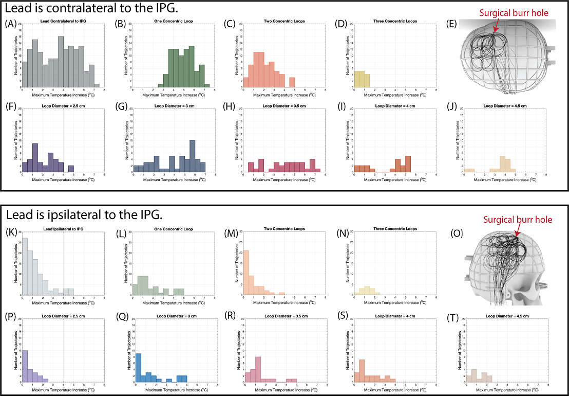
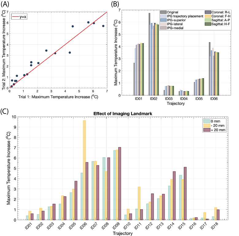
The mean ± standard deviation of ΔTmax was 3.44±1.93 oC for leads that were contralateral to the IPG and 1.26±1.17 oC for leads that were ipsilateral to the IPG (Figures 3A and 3K). As the number of concentric loops increased from one to three in contralateral trajectories, ΔTmax decreased (R=-0.83) (Figures 3B-D, L-N). Low heating trajectories contained concentric loops concentrated near the surgical burr hole, especially for leads that were contralateral to the IPG (Figures 3E and 3O). However, the diameter of the trajectory loops did not correlate with ΔTmax (R=0.17) (Figures 3F-J, P-T). The repeated experiments demonstrated excellent reliability (ICC= 0.96).Altering the imaging plane and the IPG configuration had a minimal effect on ΔTmax. The mean ± standard deviation in |ΔTmax2-ΔTmax1| was 0.66±0.52 oC across all experimental configuration changes, where ΔTmax1 corresponded to the original configuration (Figure 4B). Figure 4C shows the ΔTmax at three imaging landmarks. The mean ± standard deviation in |ΔTmax2-ΔTmax1| was 0.52±0.98 oC, where ΔTmax1 corresponded to the central landmark.
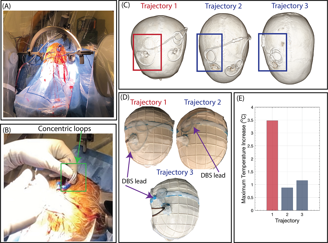
Based on the findings from the phantom experiments, DBS lead trajectories with 2-3 concentric loops near the burr hole were implemented in two new patients. Phantom experiments with the Abbott DBS system mimicking the trajectories obtained from patient CT images yielded a ΔTmax of 0.88 and 1.16 oC compared to 3.48 oC for an unmodified trajectory (Figure 5).
Discussion and Conclusion
We performed the first large-scale study to evaluate how characteristics of the extracranial DBS lead trajectory affect RF heating and to quantify the extent of RF heating reduction by surgical modification of the lead trajectory. Results from the phantom experiments demonstrated that the number of concentric loops and the position of the loops are driving factors of ΔTmax. Preliminary clinical results showed that modifying the extracranial DBS lead trajectory is surgically feasible without imposing a time burden and produces almost a 4-fold reduction in RF heating even with a high-SAR pulse sequence. Overall, surgically modifying the extracranial DBS lead trajectory while focusing on increasing the number of concentric loops and the loops’ placement can effectively mitigate RF heating during 3 T MRI.Acknowledgements
This work was supported by NIH grants R01EB030324 and T32EB025766.References
1. Falowski S, Safriel Y, Ryan M, et al. The Rate of Magnetic Resonance Imaging in Patients with Deep Brain Stimulation. Stereotact. Funct. Neurosurg. 2016; 94(3): 147-153.
2. Golestanirad L, Kirsch J, Bonmassar G, et al., RF-induced heating in tissue near bilateral DBS implants during MRI at 1.5 T and 3T: The role of surgical lead management. Neuroimage. 2019;184:566–576.
3. Mattei E, Triventi M, Calcagnini G, et al. Complexity of MRI induced heating on metallic leads: Experimental measurements of 374 configurations.Biomed Eng Online 2008;7:11.
4. Baker K, Tkach T, Hall J, et al. Reduction of magnetic resonance imaging-related heating in deep brain stimulation leads using a lead management device. Oper. Neurosurg. 2005;57(no. 4 SUPPL).
5. Golestanirad L, Angelone L, Iacono M, et al. Local SAR near deep brain stimulation (DBS) electrodes at 64 and 127 MHz: A simulation study of the effect of extracranial loops. Magn. Reson. Med. 2017;78(4):1558–1565.
Figures