0604
An Implant-Friendly Coil System for Imaging Deep Brain Stimulation at 3T MRI1Institute of Medical Physics and Radiation Protection, TH Mittelhessen University of Applied Sciences, Giessen, Germany, 2Department of Radiology and Department of Biomedical Engineering, Northwestern University, Chicago, IL, United States
Synopsis
Keywords: Safety, Safety
A prototype of an adjustable DBS-friendly Tx/Rx 3T coil system was built and evaluated with measurements and numerical simulations characterizing its image quality and SAR profile. The work envisions the use of novel MRI hardware that will make 3T MRI fully accessible to patients with DBS implants.Introduction
Deep brain stimulation (DBS) of the human brain is a remarkable technique that can treat the symptoms of several major debilitating neurological and psychiatric disorders [1-4]. While the clinical utilities of DBS have grown exponentially, its underlying therapeutic mechanisms of action remain controversial. Due to its superb soft tissue contrast and high-resolution visualization of the brain’s anatomy, MRI is excellently poised to address certain problems about targeting and mechanisms of DBS. Unfortunately, the interactions between the radiofrequency fields of MRI scanners and DBS leads can result in restrictive safety hazards that limit the accessibility of MRI for patients with DBS implants. In our previous study, the feasibility of a rotating birdcage transmitter has been shown to greatly reduce the specific absorption rate (SAR) during imaging of patients with deep brain stimulation implants at 1.5 T [5]. Here we present the first prototype of a DBS-friendly Tx/Rx coil system at 3T MRI, along with the results of measurements and comprehensive numerical simulations that characterize its image quality and SAR profile. The presented work anticipates deploying novel MRI hardware that will enable 3T MRI accessible to DBS patients in its full capacity.Methods
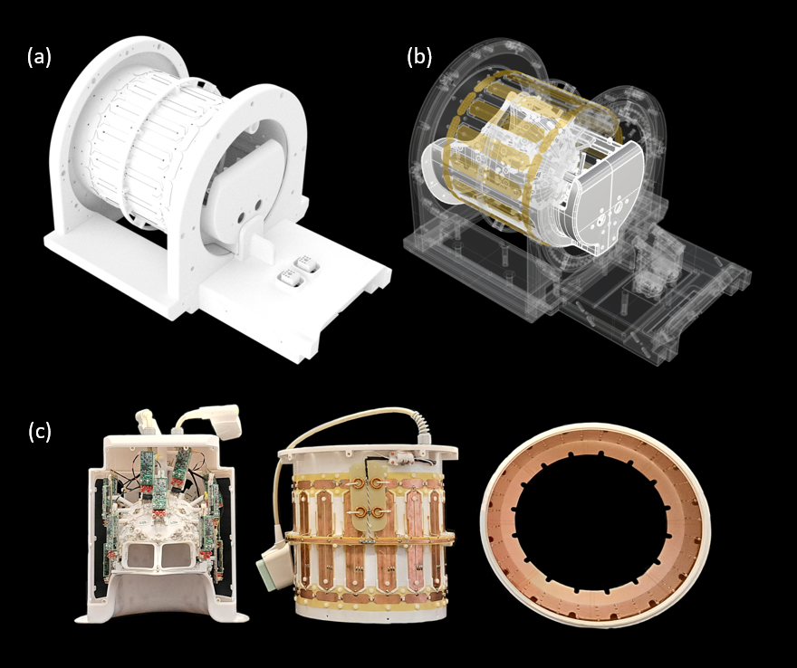
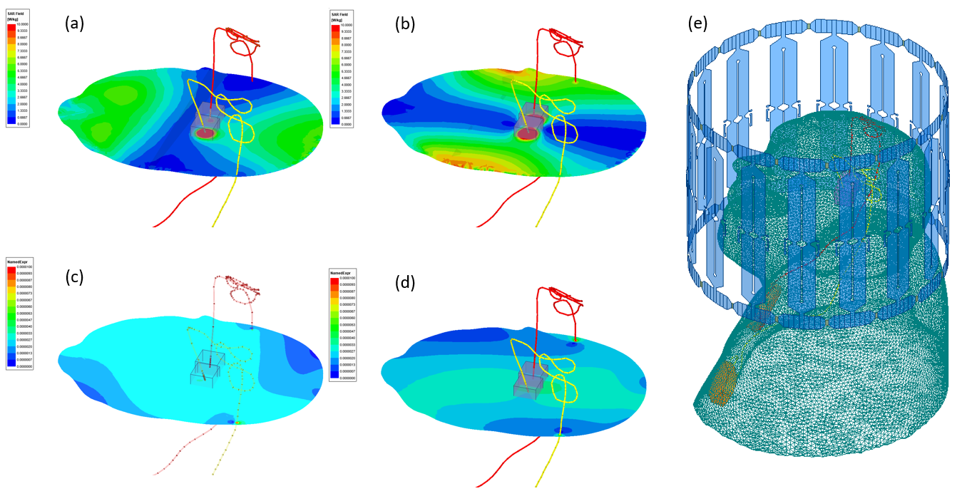
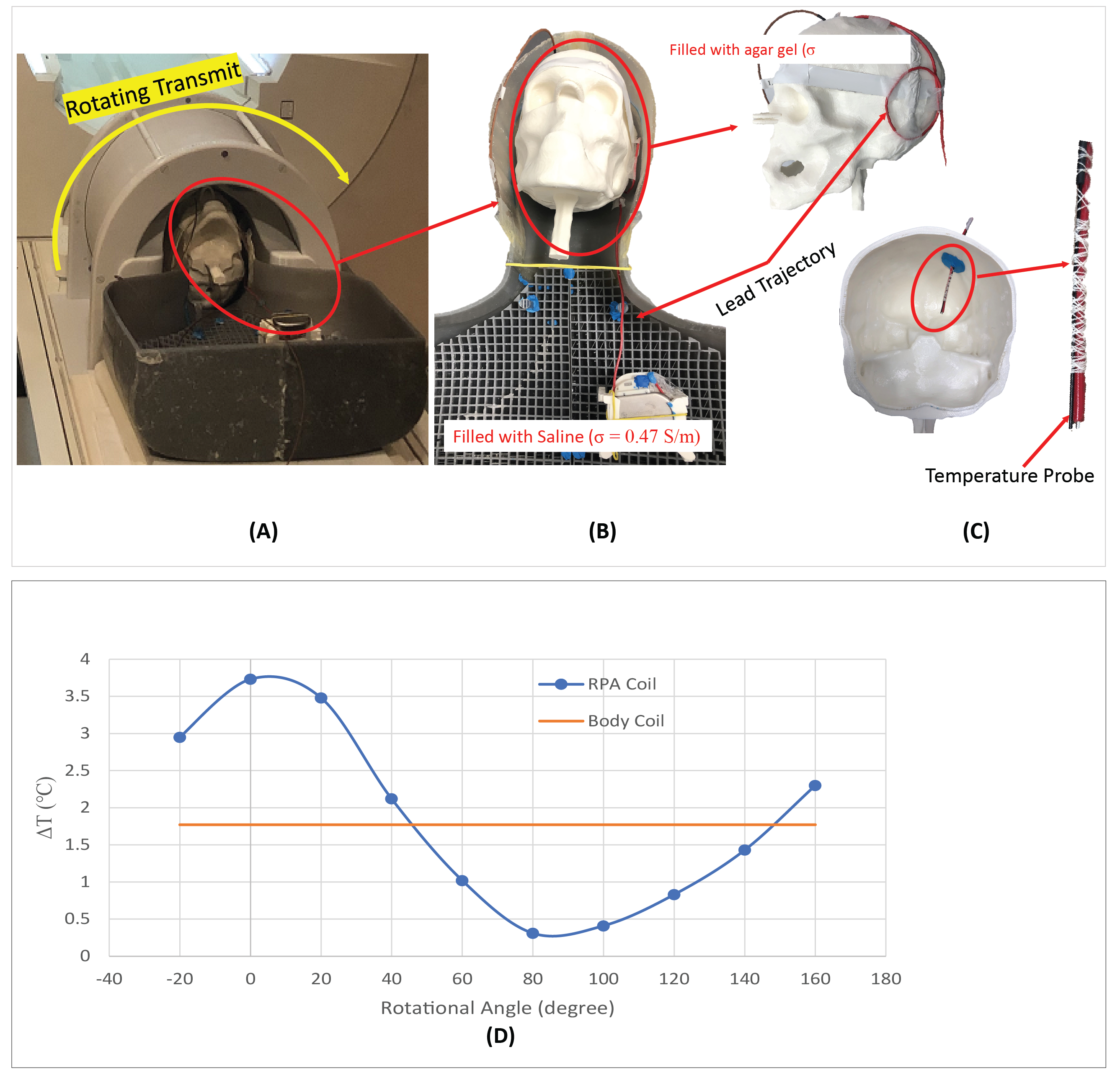
Hardware design and construction: The 3T coil system was composed of a linearly-polarized rotating high-pass birdcage transmitter, and an anatomical conformal 32-channel receive array (see Fig.1). Uniquely, the transmitter has a slab-like region of low electric field that can be co-aligned with the patient’s individual lead trajectory to encompass the DBS implant. This technique highly reduces the local SAR at the implant tip. An array of 32-channel surface receiver coils was designed for employing highly accelerated brain imaging, such as GRAPPA [6] or simultaneous multislice (SMS) [7,8] methodologies. The coil ensemble went through a comprehensive battery of safety tests to assess the quality of active detuning and SNR maps, as well as evaluating the potential temperature increases due to eddy-currents and RF absorption.Numerical models: A simulation-based finite element method (FEM) approach with the software package ANSYS Electronic Desktop (HFSS 19.2, ANSYS Inc., Canonsburg, PA.), was used to assess the transmission characteristics of the rotating LP birdcage coil. Tuning and matching of the birdcage coil at the 3T Larmor frequency was achieved by linking the embedded circuit designer with the HFSS model. Patient-specific simulations were performed on 2 realistic DBS lead trajectories, extracted from post-operative CT images of patients. The simplified models consisted of human head like tissue (εr= 78; σ = 0.47 S/m), the electrodes consisted of Pt-Ir (εr= 1; σ = 4*10^6 S/m), and their Insulation of Urethane (εr =3.5; σ = 0 S/m). The meshing all numerical models was automatically adjusted by the FEM solver until it achieved the set accuracy threshold. All simulations converged within 6 Passes and a convergence criteria of ΔS = 0,02. In total 32 simulations were performed on two different patient models with different trajectory paths of the DBS leads and unequal number of implanted pulse generators (IPG). Two patient simulations with a conventional CP birdcage body coil were performed for comparison, one for each patient model. The RF heating was measured in an anthropomorphic 3D printed phantom model (Figure 3). The skull was filled with NaCl-doped agar gel and the torso was filled with saline, both having conductivity of 0.47 S/m. We measured the heating during T1-TSE sequence (B1+rms = 1.8 µT) in the constructed DBS-friendly coil system and in the regular CP body coil (Figure 3).
Results
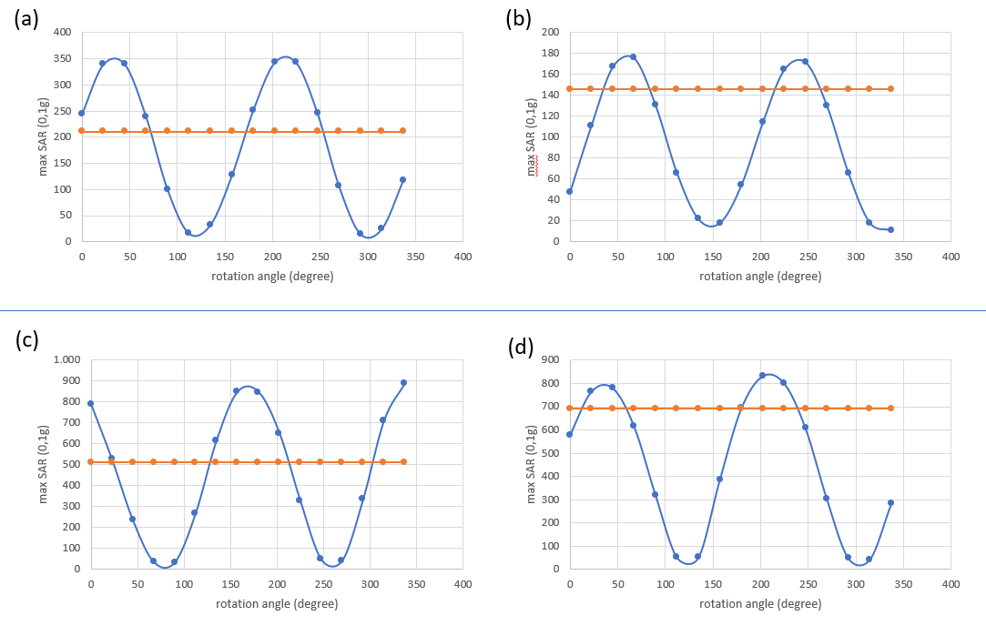
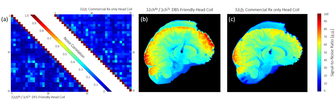
The 32-channel DBS-friendly coil showed slight SNR improvement when compared with the standard 32-channel head coil (Figure 5) and is well-suited for modern neuro-MR imaging sequences. The simulation of the LP birdcage coil has shown that the max SAR (0.1g) can be reduced significantly by a factor of 14-15x for both simulated patient models, when compared with regular CP body coil. Temperature measurements in the anthropomorphic phantom setup confirmed this characteristic. However, depending on the rotation angle of the LP birdcage coil, the max SAR could be amplified up to 180% of the CP mode of the body coil. Measurements in the DBS phantom setup showed a temperature increase of only 0.5°C for the optimum angle of the transmit coil.Conclusion
A first prototype of a DBS-friendly Tx/Rx coil system at 3T MRI was designed, constructed, and validated. The coil showed substantial SAR reduction at the optimum rotation angle, suggesting that it is well suited for imaging patients with DBS implants.Acknowledgements
No acknowledgement found.References
[1] McIntyre CC, Savasta M, Kerkerian-Le Goff L, Vitek JL. Uncovering the Mechanism(s) of Action of Deep Brain Stimulation: Activation, Inhibition, or Both. Clin. Neurophysiol. 2004;115:1239–1248.
[2] Herrington TM, Cheng JJ, Eskandar EN. Mechanisms of Deep Brain Stimulation. J Neurophysiol. 2016;115:19–38.
[3] Udupa K, Chen R. The Mechanisms of Action of Deep Brain Stimulation and Ideas for the Future Development. Prog Neurobiol. 2015;133:27–49.
[4] Chiken S, Nambu A. Mechanism of Deep Brain Stimulation: Inhibition, Excitation, or Disruption? Neuroscientist. 2016;22:313–322.
[5] Golestanirad L, Keil B, Angelone LM, Bonmassar G, Mareyam A, Wald LL. Feasibility of using linearly polarized rotating birdcage transmitters and close-fitting receive arrays in MRI to reduce SAR in the vicinity of deep brain simulation implants. Magn Reson Med. 2017 Apr;77(4):1701-1712
[6] Griswold MA, Jakob PM, Heidemann RM, Nittka M, Jellus V, Wang J, Kiefer B, Haase A. Generalized Autocalibrating Partially Parallel Acquisitions (GRAPPA). Magn. Reson. Med. 2002;47:1202–1210.
[7] Feinberg DA, Moeller S, Smith SM, Auerbach E, Ramanna S, Gunther M, Glasser MF, Miller KL, Ugurbil K, Yacoub E. Multiplexed Echo Planar Imaging for Sub-Second Whole Brain FMRI and Fast Diffusion Imaging. PLoS ONE. 2010;5:e15710.
[8] Setsompop K, Gagoski BA, Polimeni JR, Witzel T, Wedeen VJ, Wald LL. Blipped-Controlled Aliasing in Parallel Imaging for Simultaneous Multislice Echo Planar Imaging with Reduced g-Factor Penalty. Magn. Reson. Med. 2012;67:1210–1224.
Figures