0603
Lead Insulation and Wavelength Effects on Active Implantable Medical Device Heating under MRI at 1.5T and 3T using Transfer Function (TF) Modeling
Ananda Kumar1, Ji Chen2, Md Zahidul Islam2, and Hongbae Jeong1
1CDRH, Food and Drug Administration, Silver Spring, MD, United States, 2Department of Electrical and Computer Engineering, University of Houston, Houston, TX, United States
1CDRH, Food and Drug Administration, Silver Spring, MD, United States, 2Department of Electrical and Computer Engineering, University of Houston, Houston, TX, United States
Synopsis
Keywords: Safety, Safety
The influence of the thickness, loss tangent value of the lead insulation material along with lead length effects on the heating of an active implantable medical device (AIMD) lead electrode is analyzed using full-wave EM simulations. Decreasing the thickness of the insulation decreases heating of the electrode significantly when lead lengths are less than or equal to wavelengths in the medium. Increasing the loss tangent of the insulation material has a moderate effect in reducing heating at the electrode. Standing wave distortions affect lead electrode heating at lead lengths greater than wavelengths in the medium.Introduction
Induced currents on the leads of the AIMDs under MRI RF transmit fields results in heating on the leads, electrodes and implantable pulse generators (IPG) posing risks to patients with AIMDs. The transfer function (TF) method is a state-of-the-art approach to analyze AIMD heating under MRI. The TF method overcomes the massive computational challenge of modeling highly intricate geometry of AIMDs placed inside heterogenous dielectric human body models. AIMD heating in the MRI environment is predicted in a two-step process: (i) by either modeling or measuring the TF; (ii) by numerically calculating the electric (E) fields in human body models without the presence of AIMD1. In this study the influences of the thickness, lossy property of the insulation material – i.e., loss tangent, tan δ (σ/(ωε)), and the lead length relative to the wavelengths (λ64MHz, λ128 MHz) in the medium on the heating of straight wire AIMD leads are explored using full-wave electromagnetic (EM) modeling of the heating TFs2 employing the reciprocity principle.Methods
AIMDs with a 10 mm long electrode section connected to straight wire leads (lengths 45cm ~ λ64MHz, 65cm > λ64MHz at 64 MHz and 25 cm ~ λ128 MHz, 45 cm > λ128 MHz at 128 MHz) were modeled and excited with 1 A sources at 64 MHz and 128 MHz placed at 2 mm distance from the electrode tip to determine heating TFs. For insulation thickness analysis Polyethylene Terephathalate (PET) material (ε = 2.8) was used and for lossy insulation loss tangent values (tan δ = 0.005 to 0.1, typical to that of silicon, neoprene rubber) were explored. Simulations and experiments were performed in a rectangular ASTM phantom containing dielectric medium (σ = 0.47 S/m; ε = 78). Current distributions on the leads were numerically evaluated using the Method of Moments with surface equivalence principle (FEKO, Altair, USA). An experimental validation of the numerical simulation was done with a straight wire lead of 65 cm length with 64 cm insulation and 1 cm bare wire at the excitation end. Straight lead was excited 2 mm away from the bare wire end and current measurements were performed with a current sensor (Pearson Electronics, Palo Alto, CA), using a vector network analyzer as shown in Fig. 1Results
TF shapes in Fig.2 (a) and (c) show that decreasing the insulation thickness significantly (up to 50%) decreases heating of the electrodes and along the leads for lead lengths shorter than or equal to the wavelengths in the medium. Electrode heating is reduced on thinly insulated leads due to an increase in the leakage currents along the lead length3. For lead lengths significantly higher than wavelengths in the medium (Fig.2 (b) and (d)), TF shapes indicate standing wave distortions. In Fig.3, TF shapes predict decreased heating at the electrodes as the loss tangent of the insulation material is increased. Electrode heating is only moderately reduced by increasing the leakage currents along the lossy insulation material. Also, standing wave distortions occur for lead lengths greater than the wavelengths in the medium. Fig.4 show experimental validation of simulation findings (see Fig. 2 (b) and (d)) on the influence of decreasing insulation thickness and wavelength effects on reducing heating on lead and electrodes of AIMDs. Current values at excitation points vary between simulation to experiment due to variability in the source location from the bare electrode section.Discussion
The impedance mismatch conditions at the distal ends of leads where IPGs attach cause standing wave distortions. By appropriately mating the IPGs’ input impedances to the leads’ impedances, the AIMD heating could be minimized by reducing the thickness and increasing the loss tangent of the insulation material. We observe good correlation between experimental and simulation results.Conclusion
In this study we demonstrated the potential utility of EM simulations to investigate the influences of lead thickness, insulation material loss tangent, and lead lengths on AIMD heating. Further work will be done involving simulation and experimental validations with E-field calculations, current measurements, and temperature measurements in an appropriate phantom under MRI body coil exposure.Disclaimer
The mention of commercial products, their sources, or their use in connection with material reported herein is not to be construed as either an actual or implied endorsement of such products by the Department of Health and Human Services.Acknowledgements
References
1. S. Park, R. Kamondetdacha and J. Nyenhuis, "Calculation of MRI-induced heating of an implanted medical lead wire with an electric field transfer function," J. Magn. Reson. Imag., vol. 26, no. 5, pp. 1278-1285, 2007.
2. Feng Shi, Rui Qiang, Wolfgang Kainz, and Ji Chen. "A Technique to Evaluate MRI-induced Electric Fields at the Ends of Practical Implanted ead." IEEE Transactions on Microwave Theory and Techniques 63, no. 1 (2014): 305-313.
3. P.A. Bottomley, A Kumar, W.A. Edelstein, J.M. Allen, P.V. Karmarkar, “Designing Passive MRI-Safe implantable conductive leads with electrodes”, Medical Physics, vol 37, issue 7, part 1, July 2010.
Figures
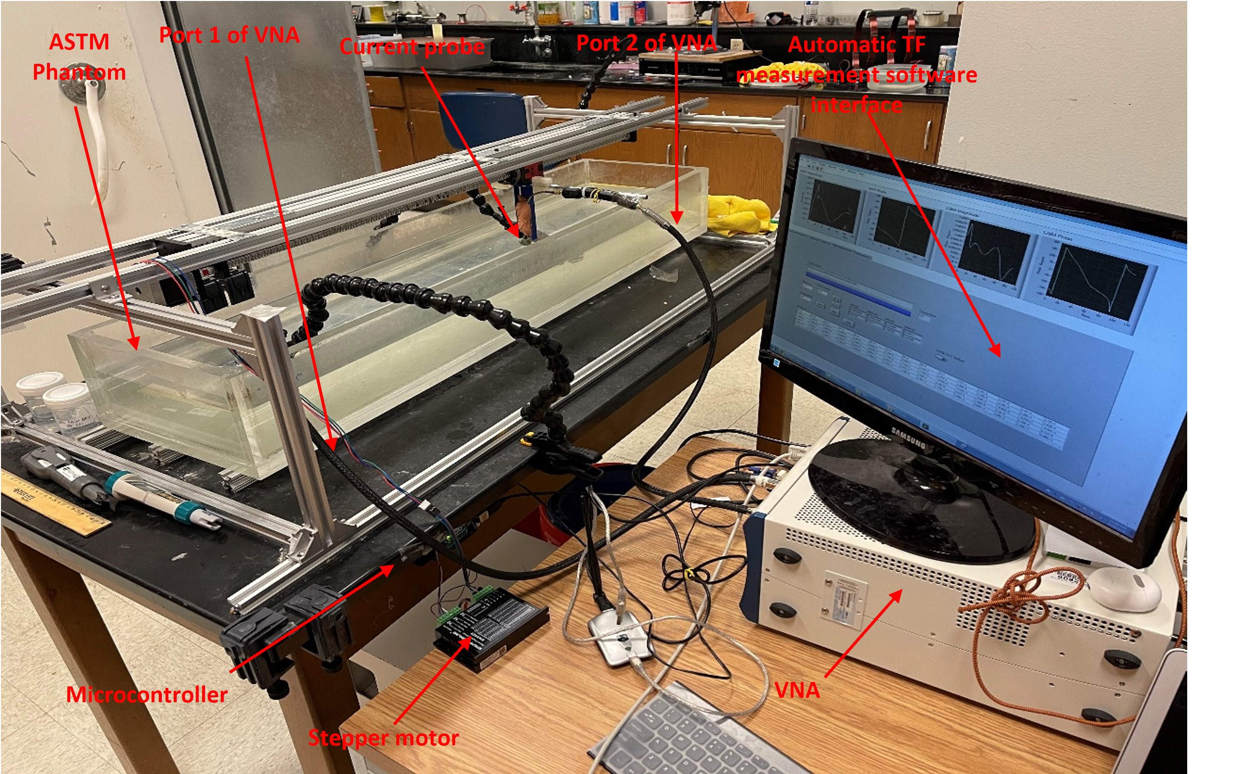
Figure 1. Illustration of
transfer function measurement setup. Z axis along the length of the phantom and
origin at mid-point (Z=0).
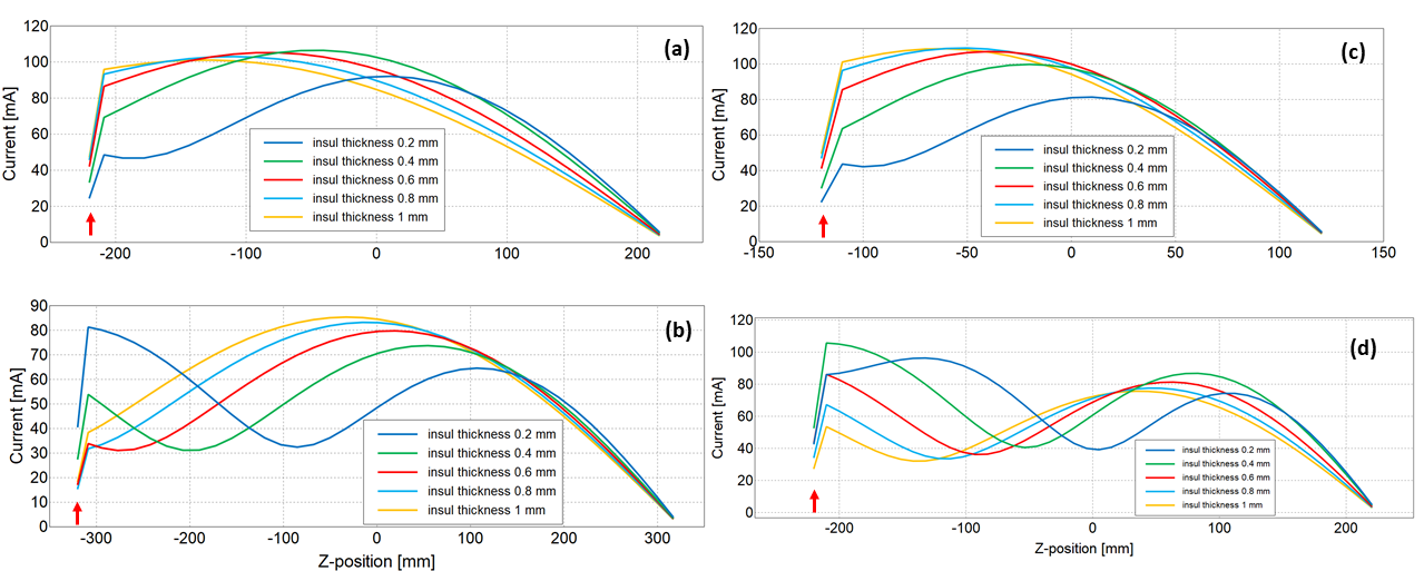
Figure 2. (a) TFs of straight wire leads of length 45cm ~ λ64MHz; (b) 65 cm > λ64MHz as insulation (σ = 0; ε = 2.8) thickness
was varied at 64 MHz; (c) TFs of straight wire leads of length 25cm ~ λ128 MHz ; (d) 65 cm > λ128 MHz as insulation (σ = 0; ε = 2.8)
thickness was varied at 128 MHz. Red arrows indicate locations of excitation at electrodes.
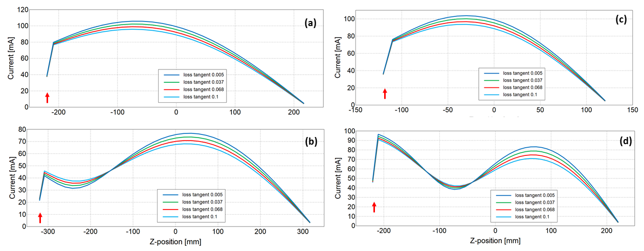
Figure 3. (a) TFs of straight wire leads of length 45 cm ~ λ64 MHz ; (b) 65 cm > λ64 MHz as insulation loss tangent value is
varied at 64 MHz with insulation thickness of 0.5 mm; (c) TFs of straight wire leads of length 25 cm ~ λ128 MHz ; (d) 45 cm > λ128 MHz as insulation loss tangent value is
varied at 128 MHz with insulation thickness of 0.5 mm.
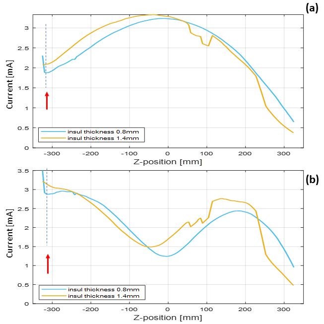
Figure 4. Experimental validation of the influence of reducing insulation
thickness on heating of the 65 cm lead at (a) 64 MHz and (b) 128 MHz (Compare simulation at 64 MHz (Fig.2(b)) and 128 MHz (Fig.2(d))).
DOI: https://doi.org/10.58530/2023/0603