0602
Simulated and experimental approaches to perfusion cooling in Sim4Life: verification and applications to RF heating of implants1Medical Biophysics, University of Western Ontario, London, ON, Canada, 2Physics & Astronomy, University of Western Ontario, London, ON, Canada
Synopsis
Keywords: Safety, Safety, RF heating, perfusion, Experimental, verification
Perfusion cooling of implants is an emergent field that has the potential to greatly improve patient access to MRI for those living with implants that previously failed the radiofrequency heating test (ASTM F2182). Many implants fail by a small margin, meaning they would likely be safe inside the body when perfusion is considered. Here, we present initial steps for the experimental verification of perfusion simulations in Sim4Life, which showed reasonable agreement and provided some insight on future experimental perfusion platforms. From there, a perfusion cooling factor can be quantified for use during regulatory approval of these implants.Introduction
The current state of the art test for radiofrequency heating of implants (ASTM F2182-19a) uses a rectangular box phantom filled with a gelled saline, vaguely resembling the dielectric properties of the body. A gelling agent is intentionally introduced to eliminate convection cooling within the phantom, essentially equivalent to neglecting perfusion in the body1. The simplistic nature of the current phantom leads to ‘worst case scenario’ heating of implants; as high as 45 °C in some orthopedics, and can often preclude that patient from undergoing MRI2. However, there exists a subset of orthopedic IMDs that ‘fail’ the current heating test by exceeding the acceptance threshold by a small margin (Implant ΔT = 8-9 °C, Threshold = 4-5 °C). It is hypothesized that such IMDs are not truly a hazard to the patient but are likely failing due to the conservative nature of the current ASTM phantom (i.e., neglecting perfusion). That said, very little work has been done on quantifying perfusion cooling of implants experiencing RF heating, most perfusion work has been related to tissue warming during lengthy scans 3–5.Quantifying perfusion cooling of implants would require simulations of dynamic perfusion cooling in the body, which upregulates blood flow in response to tissue heating. Simple (i.e., static) simulated perfusion must first be experimentally verified before we can fully rely on dynamic perfusion simulations. Thus, the objective here was the experimental verification of simulated perfusion cooling using a prototype perfusion phantom.
Methods
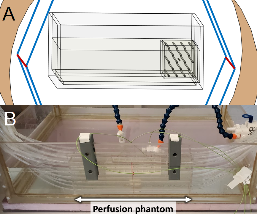
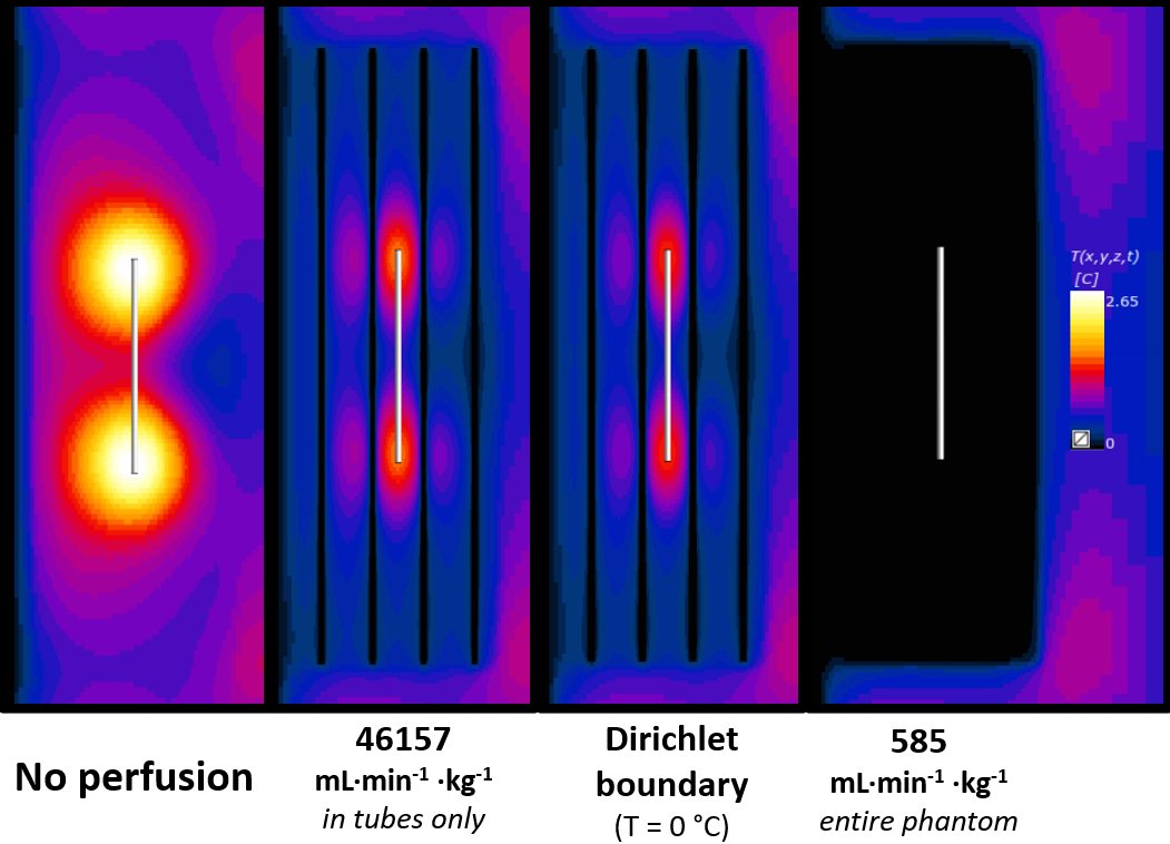
Since we would ultimately be using Sim4Life; which uses the Pennes Bioheat Equation (PBE) as its’ thermal solver, an experimentally valid equivalent of the PBE was required. A perfusion phantom (Figure 1B) was adapted from a previously published model shown to behave like the PBE6. The perfusion phantom is a 10 x 10 x 30 cm box with 18 equally spaced parallel tubes, placed inside the existing ASTM phantom. The ASTM standard 10 cm titanium rod was chosen as the sample implant for this verification testing. The entire perfusion set up was tested inside our benchtop RF exposure platform (Medical Implant Test System, Zürich MedTech) at both 64 and 128 MHz, at an approximate WB-SAR of 1.5 W/kg.This setup was emulated in Sim4Life using 2mm resolution, and 1 x 1 x 2 mm subgridded resolution for the tubing and the titanium rod. Three perfusion approaches were utilized in the thermal simulations: (1) Traditional PBE perfusion (i.e., 585 mL∙min-1∙Kg-1 heatsink, entire phantom), (2) Perfusion only in tubes (scaled up to 46,157 mL∙min-1∙Kg-1 to account for difference in mass), and (3) Setting tubes to a Dirichlet boundary (T = 0 °C). Peak temperatures are presented at both the titanium rod and at the nearest adjacent tube.
Results
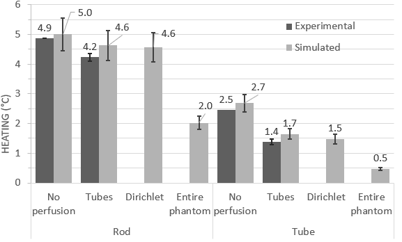
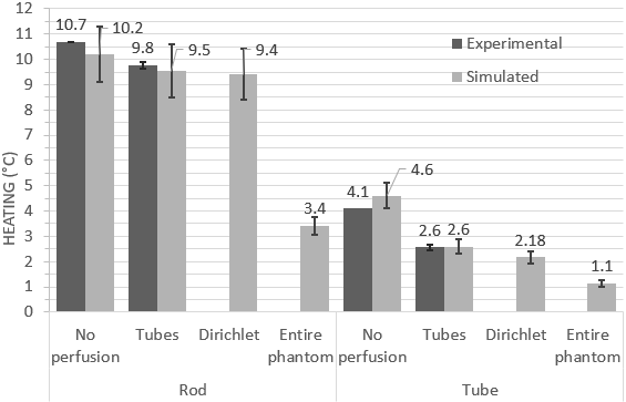
At both frequencies and temperature monitoring locations, the best agreement between experimental heating at simulated perfusion was seen with the ‘tubes only’ approach, while the Dirichlet approach was also comparable (Figures 3 and 4). Perfusion cooling in traditional PBE approach was much lower than what was seen experimentally, with strong heatsink-like behavior shown in Figure 2 alongside the other approaches. Experimental error bars represent standard deviation, while simulations show previously published uncertainty associated with Sim4Life (±10.9%)3Discussion
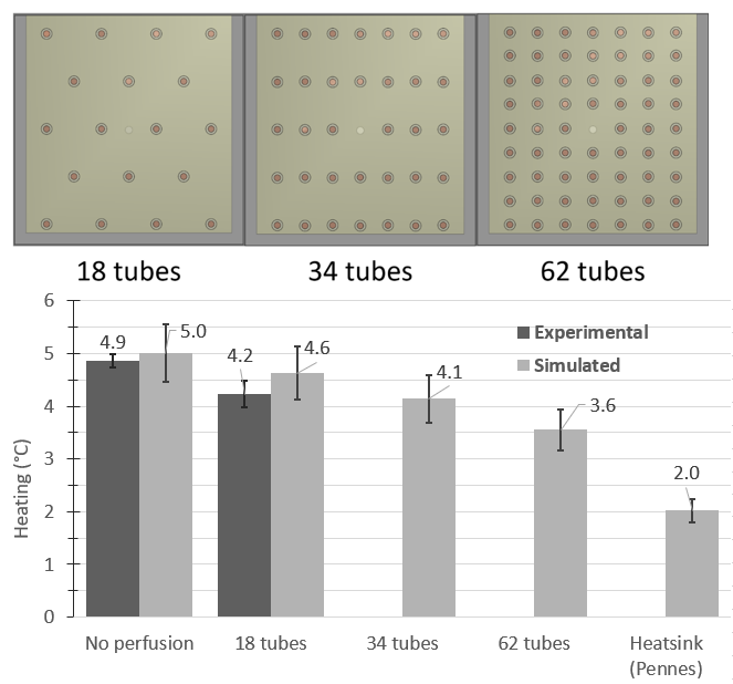
Conservation of energy explains the excellent agreement seen between the ‘tubes only’ simulations and experimental data, while the discrepancy seen with the traditional PBE method is likely due to perfusion phantom design choices. The original phantom had a higher tube density (>140), but the authors also presented a range of valid tube spacings/diameters for PBE-equivalent behavior, and our phantom was within this range. Our results suggest the range of valid tube spacings is narrower than previously thought, and our phantom was too ‘coarse’ to be a suitable PBE-equivalent. Exploratory simulations at 64 MHz suggest more PBE-equivalent behavior with increasing tube density (Figure 5).Conclusions
Previous simulation work has demonstrated that perfusion cooling has potential for substantial reduction of implant heating (40-50%), but further work is needed on improving the agreement between experimental and simulated perfusion before trusting simulated results. This will require a perfusion phantom with more tubing (Figure 5) to better mimic the PBE, but this modification comes with its own challenges involving implant positioning and flow rates. Successful experimental verification of these simulations will pave the way for the quantification of a perfusion cooling factor, which could mean the difference between failing and passing this test. Anecdotal evidence of IMD RF heating tests in our lab suggests that many orthopedic devices typically peak at ΔT = ~10 °C, which essentially precludes the patient from being scanned within a particular distance of the bore. In cases like this, a simple perfusion reduction factor of 2 would bring the heating in most of these orthopedic devices down to the acceptable threshold, possibly impacting millions of patients worldwide living with these sorts of implants.Acknowledgements
I'd like to acknowledge Frank Van Sas & Brian Dalrymple for their support with designing and fabricating the perfusion phantom, as well as Krzysztof Wawrzyn for his assistance with experimental testing using the MITS.References
[1] “Standard Test Method for Measurement of Radio Frequency Induced Heating On or Near Passive Implants During Magnetic Resonance Imaging.” https://www.astm.org/f2182-19e02.html (accessed Aug. 26, 2022).
[2] R. Guo et al., “Computational and experimental investigation of RF-induced heating for multiple orthopedic implants,” Magnetic Resonance in Medicine, vol. 82, no. 5, pp. 1848–1858, 2019, doi: 10.1002/mrm.27817.
[3] M. Murbach et al., “Thermal Tissue Damage Model Analyzed for Different Whole-Body SAR and Scan Durations for Standard MR Body Coils,” Magnetic Resonance in Medicine, vol. 71, no. 1, pp. 421–431, 2014, doi: 10.1002/mrm.24671.
[4] I. B. Akca, O. Ferhanoglu, C. J. Yeung, S. Guney, T. O. Tasci, and E. Atalar, “Measuring local RF heating in MRI: Simulating perfusion in a perfusionless phantom,” Journal of Magnetic Resonance Imaging, vol. 26, no. 5, pp. 1228–1235, 2007, doi: 10.1002/jmri.21161.
[5] I. Laakso and A. Hirata, “Dominant factors affecting temperature rise in simulations of human thermoregulation during RF exposure,” Phys. Med. Biol., vol. 56, no. 23, pp. 7449–7471, Nov. 2011, doi: 10.1088/0031-9155/56/23/008.
[6] J. W. Baish, K. R. Foster, and P. S. Ayyaswamy, “Perfused Phantom Models of Microwave Irradiated Tissue,” Journal of Biomechanical Engineering, vol. 108, no. 3, pp. 239–245, Aug. 1986, doi: 10.1115/1.3138609.
Figures