0599
Minimum Electric Field Gradient Array Body Coil with Adjustable Regions of Linearity1Department of Electrical and Electronics Engineering, Bilkent University, Ankara, Turkey, 2National Magnetic Resonance Research Center (UMRAM), Bilkent University, Ankara, Turkey
Synopsis
Keywords: Safety, Safety
A large region of linearity in whole-body gradient coils exposes large body areas to switching magnetic fields, inducing high electric fields, which may cause peripheral nerve stimulation. A body gradient array coil (made up of multiple coil elements) can produce linear gradients in different region of linearity shapes by optimizing the feeding currents, which can minimize the induced E-fields.Introduction
The rapid switching of magnetic fields (B-fields) induces electric fields (E-fields) within the human body, which causes peripheral nerve stimulation (PNS). A large region of linearity (ROL) in whole-body gradient coils exposes large body areas to switching magnetic fields, inducing high E-fields. However, a large ROL is not necessary for all MRI examinations. Several short-body and head-insert gradient coils1 with small ROL were developed to increase gradient strength without causing PNS. Recent gradient design algorithms incorporate constraints on the E-fields, leading to PNS-optimized gradient coils2,3. Despite these efforts, further optimization cannot be performed after coil fabrication. A body gradient array coil (made up of multiple coil elements) can produce linear gradients in different ROL shapes by optimizing the feeding currents, which can alter the induced E-fields. This work shows the performance of the gradient array coil4,5 in minimizing E-field when the desired gradient is required in various ROL.Methods
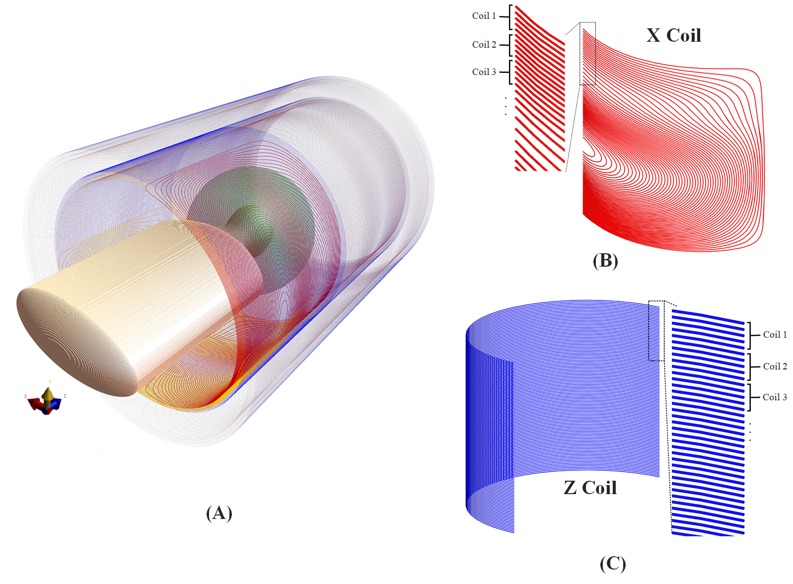
Gradient Array Body Coil: For the x- and y-coils, each quarter of a conventional design is broken down into 12 bundles that can be driven separately with different currents. The x- and y-array coils operate as a conventional gradient coil when the same currents are applied to all of their channels. The z-array coil is composed of bundles of circular loops uniformly spaced along the z-axis. The shields of the coils are designed in the same manner. Both the primary and shield arrays can be programmed to operate as a conventional gradient coil with the usual functionality. Fig.1 shows details of the coil.Field calculations: When a unit current is applied to one of the channels while the others are zero, the magnetic field profile and induced electric field on a given body model are computed using the low-frequency solvers available in Sim4Life.
Therefore, we combine the z components of the magnetic field vectors at all sample points as columns of the B-field matrix. The total magnetic field then can be expressed as the multiplication of the B-field matrix and the feeding currents:
$${B_{z-Total}}={B_{matrix}}I=\left[{\begin{array}{*{20}{c}}{{B_{z-1,1}}}&{{B_{z-1,2}}}&\cdots&{{B_{z-1,m}}}\\{{B_{z-2,1}}}&{{B_{z-2,2}}}&\cdots&{{B_{z-2,m}}}\\\vdots&\vdots&\ddots&\vdots\\{{B_{z-n,1}}}&{{B_{z-n,2}}}&\cdots&{{B_{z-n,m}}}\end{array}}\right]\left[{\begin{array}{*{20}{c}}{{i_1}}\\{{i_2}}\\\vdots\\{{i_m}}\end{array}}\right]$$
$$${B_{z-n,m}}$$$ is the z component of the magnetic field due to the mth coil (unit current) at the nth sample point.
Because E-field vector directions differ at each sample point, the E-field matrices for each component of x-, y-, and z-gradients are computed to obtain the total E-field. The total E-field is similarly calculated in vector form.
Body model: From the six body models introduced in Ref.6, we select the 50th male model for E-field calculations.
Optimization problem: We find the amplitude of the currents that minimize the E-field peak on the body model surface (fmincon solver in MATLAB’s optimization toolbox). Constraints are placed on: the magnetic field at a set of points spanning the desired ROL, the maximum tolerable magnetic field at the cryostat, available maximum current, and torque.
$$\min\,\,\,\,\,{\left\|{{E_{Total}}}\right\|_\infty}$$
$$\begin{array}{l}s.\,t.\,\,\,\,\left|{{B_{matrix}}I-{B_{desired}}}\right|\le\alpha{\left|{{B_{desired}}}\right|_{\max }}\\\,\,\,\,\,\,\,\,\,\,\,\,\,\,\left|{{B_{cryostat}}}\right|\le{B_{threshold}}\\\,\,\,\,\,\,\,\,\,\,\,\,\,\,\left|I\right|\le\,{I_{\max}}\\\,\,\,\,\,\,\,\,\,\,\,\,\,\,T\,I\,\,=\,\,0\end{array}$$
α represents the linearity error within the desired ROL:
$$\alpha\,=\,\frac{{\max\left({\left|{{B_{matrix}}I-{B_{desired}}}\right|}\right)}}{{\max\left({\left|{{B_{desired}}}\right|}\right)}}$$
The vector T includes the torque of basis elements for x and y coils when a unit current is applied at a 1-tesla uniform magnetic field (B0). This constraint forces the design to be torque-balanced.
Results
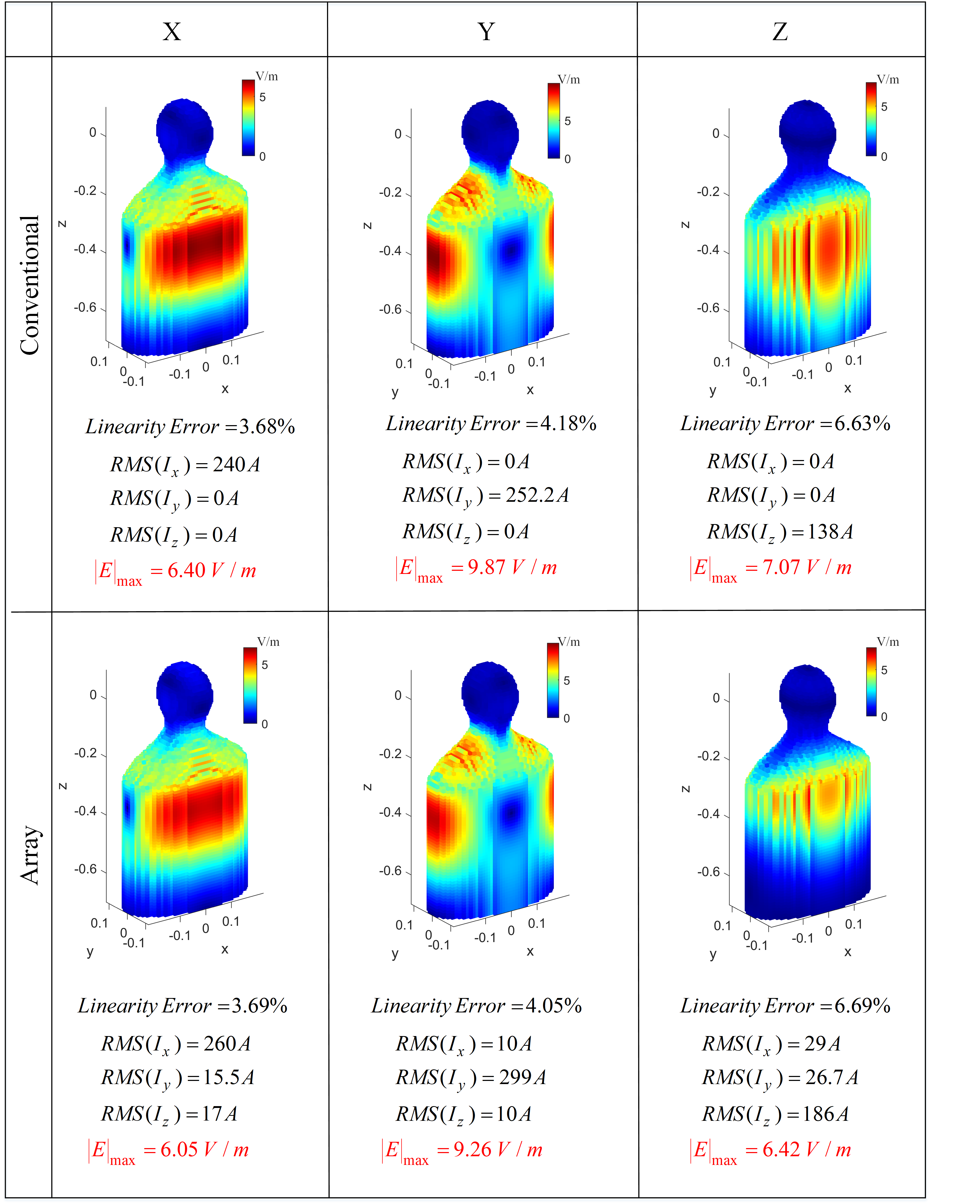
In four different cases, we demonstrate the performance of gradient array design in minimizing the E-field. In all cases, the gradient strength and slew rate are kept constant at 40 mT/m and 250 T/m/s, respectively. The performance of the shielding is also consistent across all cases. The linearity error and the currents' root mean square (RMS) are the flexible parameters. The maximum induced E-field magnitude is reported. The tested cases are:1) Spherical ROL with 225mm radius for body imaging (standard mode operation). Fig.2 demonstrates that the array coil can operate as a conventional coil with almost identical performance.
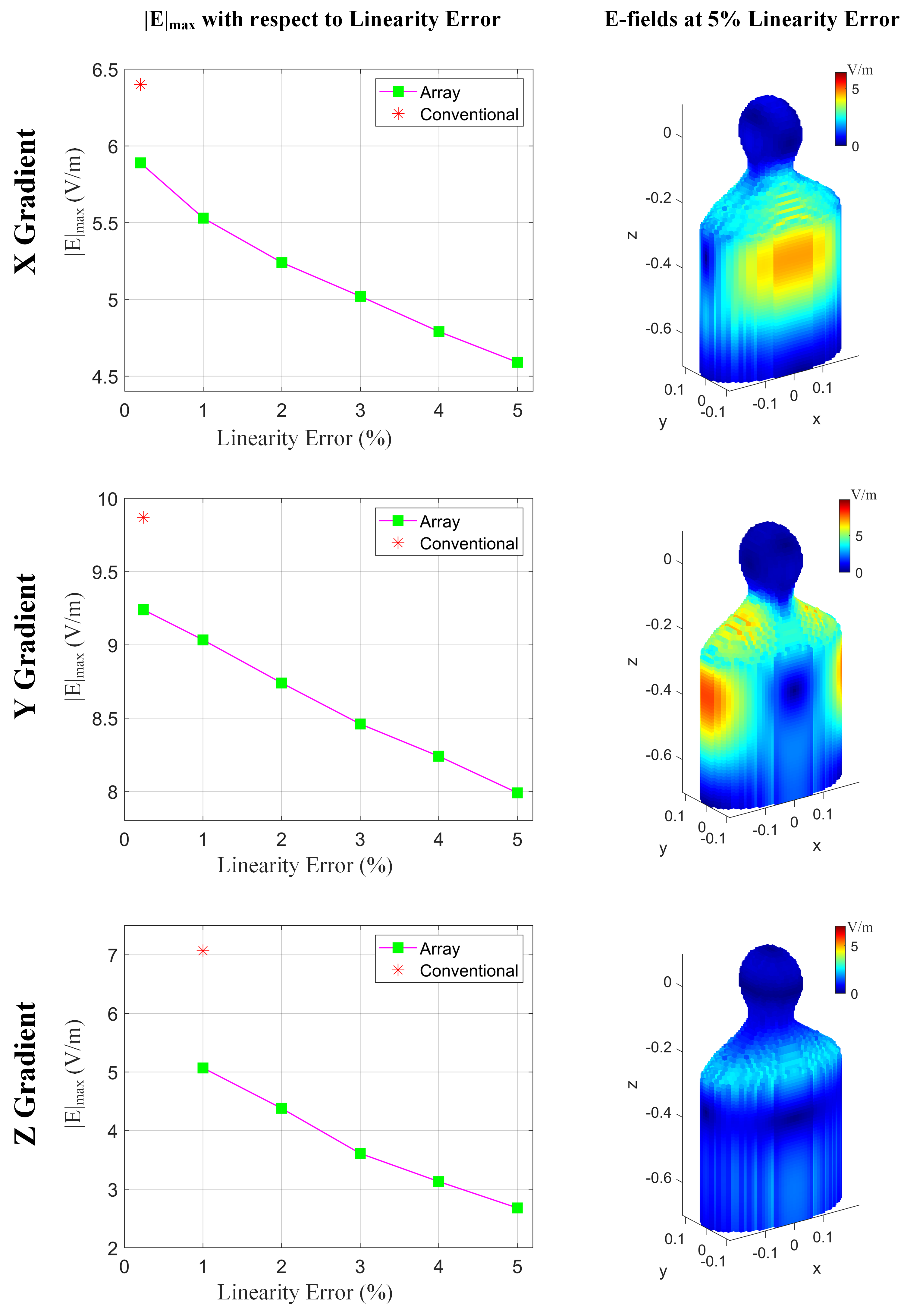
2) Spherical ROL with a 120mm radius for head-only imaging. Fig.3 shows that using the array coil, |E|max can be reduced while the other specifications remain unchanged. This figure also shows that we can significantly reduce the |E|max by relaxing the linearity error. For example, at a 5% linearity error, the E-fields are reduced up to 62%.
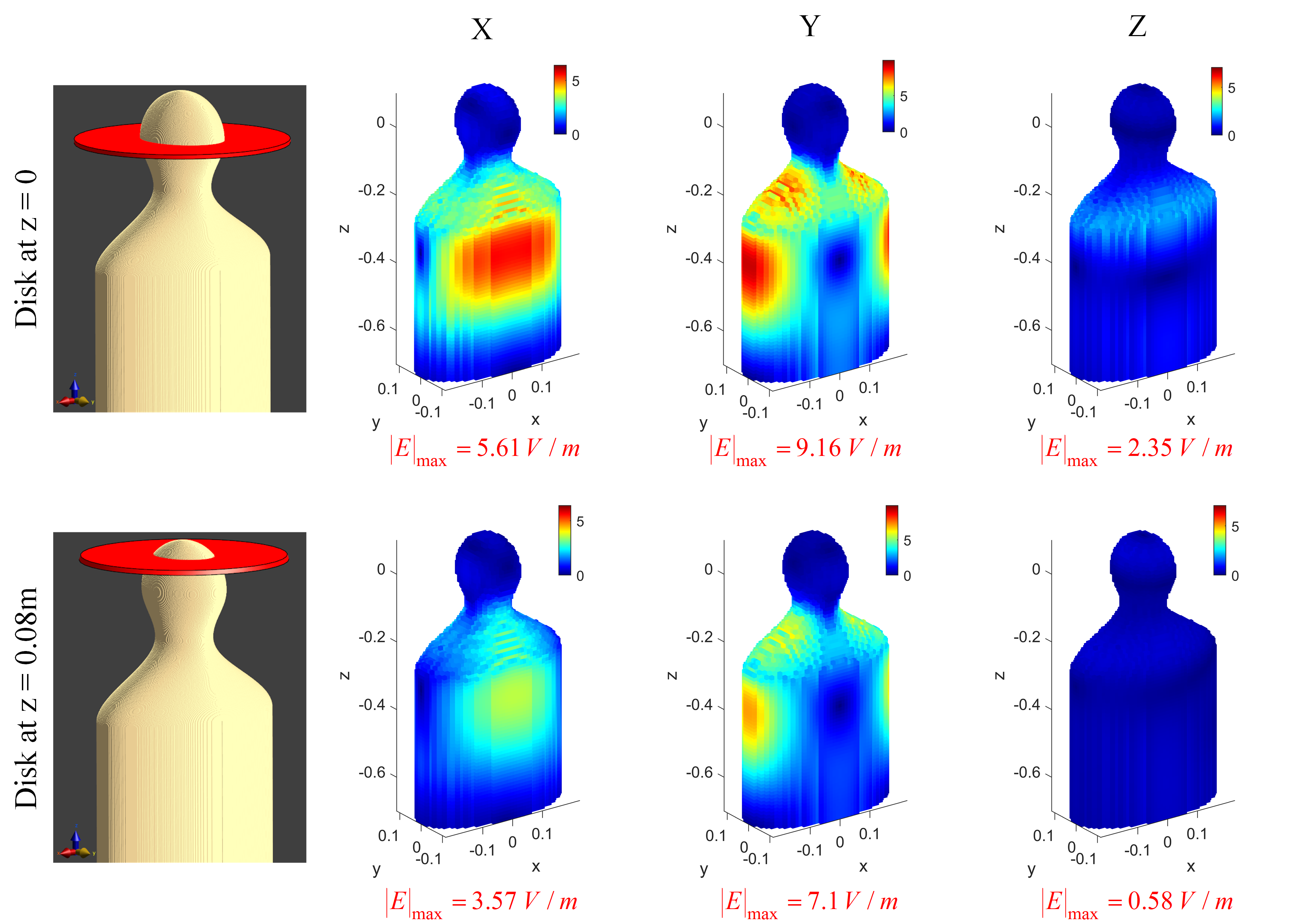
3) Disk-shaped ROL (at z=0 and z=0.08m): Fig.4 shows the performance of the array coil when the linear gradient is generated only within a z-disk. Up to 91% reduction in |E|max for the shifted disk is achieved.
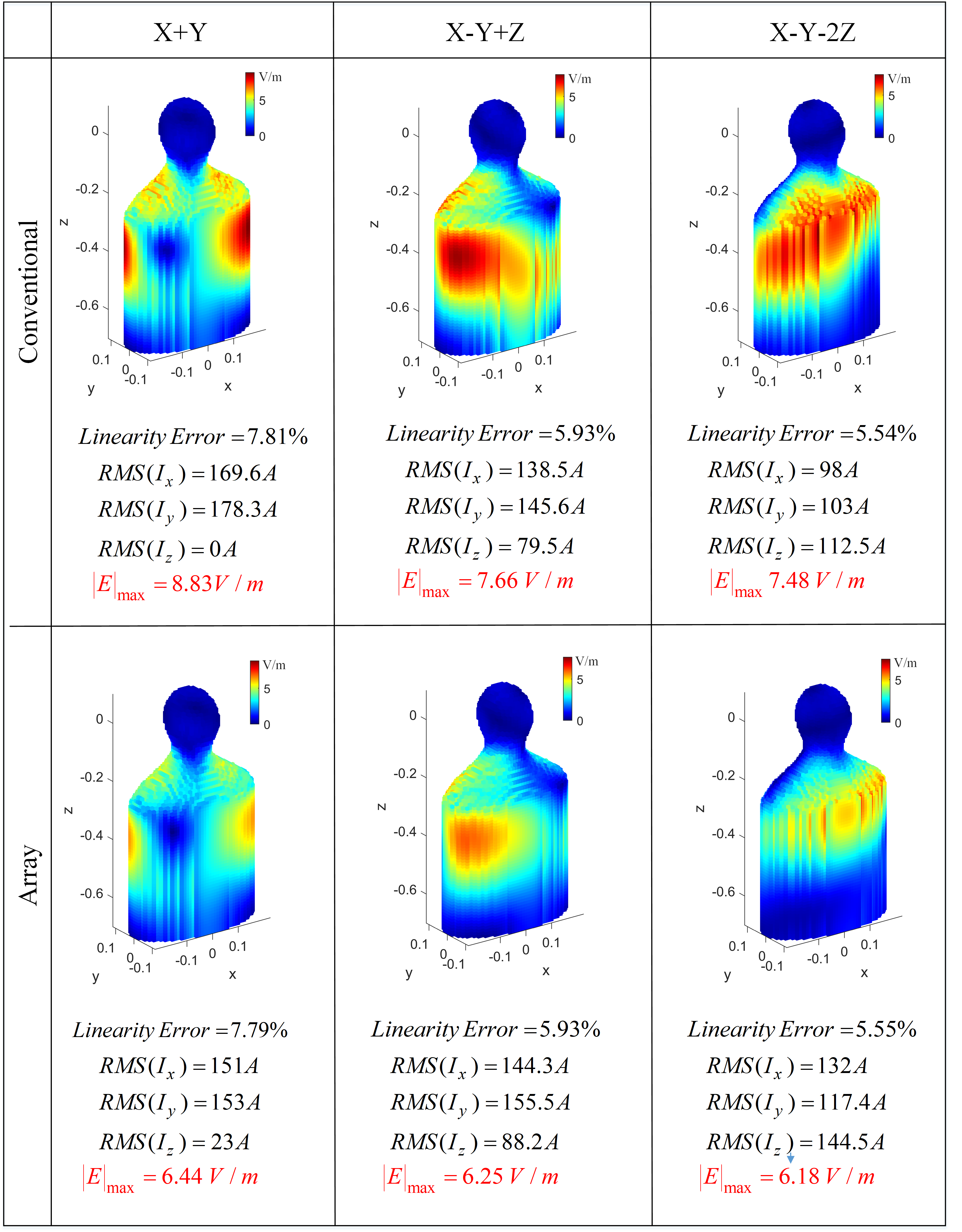
4) Oblique imaging: Fig.5 illustrates the results for an off-center oblique disk indicating that the E-field reduction technique we propose is not limited to the Cartesian coordinates.
Discussion
We demonstrated that the gradient array coil could minimize the induced E-field by generating flexible magnetic fields in various shapes of ROL. When E-fields are minimized, gradient strength and slew rate can be increased without causing PNS if required hardware is available. It is worth noting that the gradient array design consumes more power in some cases (for example, standard mode operation) to reduce the maximum E-field. We did not attempt to optimize the gradient array coil design in this preliminary work. In one mode of operation, the proposed gradient array coil could provide the same functionality and performance as a conventional coil. With an advanced gradient coil design technique, further reduction in the |E|max is expected.Acknowledgements
The authors acknowledge “Sim4Life by ZMT, www.zurichmeditech.com” for providing an Academic License.References
1. Tang F, Liu F, Freschi F, et al. An improved asymmetric gradient coil design for high-resolution MRI head imaging. Phys Med Biol. 2016;61:8875-8889.
2. Davids M, Guerin B, Klein V, Wald LL. Optimization of MRI gradient coils with explicit peripheral nerve stimulation constraints. IEEE Trans Med Imaging. 2021;40:129-142.
3. Roemer PB, Rutt BK. Minimum electric-field gradient coil design: theoretical limits and practical guidelines. Magn Reson Med. 2021;86:569-580.
4. Takrimi M, Atalar E. A z-gradient array coil with a dedicated active-shielded array coil for MRI. Magn Reson Med. 2022;1-14. doi: 10.1002/mrm.29390.
5. Babaloo R, Takrimi M, Atalar E. Increasing Peripheral Nerve Stimulation Thresholds Using Gradient Array Coils. In Proceedings of the Joint Annual Meeting of ISMRM-ESMRMB; London, 2022.
6. Roemer PB, Wade T, Alejski A, McKenzie CA, Rutt BK. Electric field calculation and peripheral nerve stimulation prediction for head and body gradient coils. Magn Reson Med. 2021;86:2301-2315.
Figures