0312
A Flexible Coil Based on a Cable Conductor for 0.55T Head Imaging1Radiology, Center for Advanced Imaging Innovation and Research (CAI2R), New York University, Grossman School of Medicine, New York City, NY, United States, 2Siemens Medical Solutions USA Inc., Malvern, PA, United States, 3Siemens Healthcare GmbH, Erlangen, Germany
Synopsis
Keywords: Low-Field MRI, Brain
Flexible coils have the potential to improve SNR over rigid coils but have been rarely applied to head imaging. We built a flexible 13-channel coil for 0.55T based on RG-223 cable loops arranged with dodecahedral geometry. The coil closely fit the head and provided 30-50% SNR gain in the ventricles and significant image quality improvements over a conventional rigid coil. While the current minimalistic prototype coil showed promising performance, practical advances, such as an insulating layer that can be easily sanitized and a structure to immobilize the head, must be integrated to make the coil user friendly.Introduction
A new-generation whole-body 0.55T MRI system has been recently cleared by the FDA for clinical imaging1,2. While its signal-to-noise ratio (SNR) is inherently lower than that of standard 1.5T and 3T machines, the 0.55T system offers improved patient comfort due to a 80-cm wide bore, and reduced magnetic field inhomogeneity and specific absorption rate that can benefit applications such as implant imaging3,4. However, spacious rigid radiofrequency coils can further compromise SNR, particularly at frequencies as low as 23.55MHz where tissue loading is weak. Flexible coils5 inherently maximize loading because they closely fit the anatomy. Nonetheless, examples of flexible head coils remain sparse6-8. We showed previously that a flexible “cable coil” provides suitable electro-mechanical features for knee imaging at 0.55T9. In this work, we developed a flexible cable coil-based array for head imaging and demonstrate SNR and image quality advantages over a conventional rigid coil.Methods
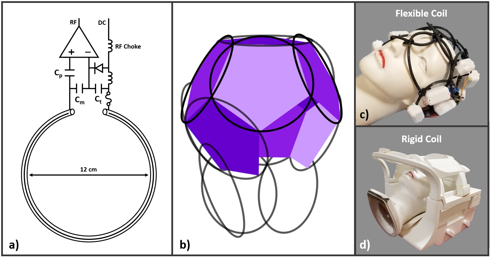
We built a flexible head coil using loops that were made to resonate at 23.55MHz by inserting a capacitor in series with the shield of RG-223 coaxial cable (part number 9273, Belden), while the center conductor remained electrically floating9 (Figure 1). We found that 12-cm loops provided sufficient loading and closely fit the head when arranged into a 13-channel coil with dodecahedral tiling, resembling that described by Wiggins et al10. The dodecahedral configuration was realized by fastening loops to one another with zip-ties, without a dedicated foundational structure. The flexible coil was evaluated on a commercial MRI system (1.5T MAGNETOM Aera; Siemens Healthcare, Erlangen, Germany) modified to operate as a prototype at 0.55T. The reference coil was a rigid 16-channel head and neck coil that originally was built for 1.5T and re-tuned to 23.55MHz.Results
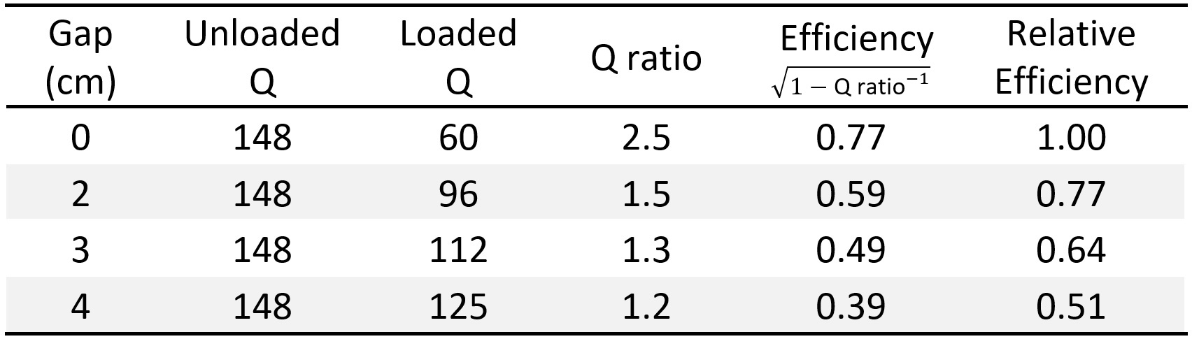
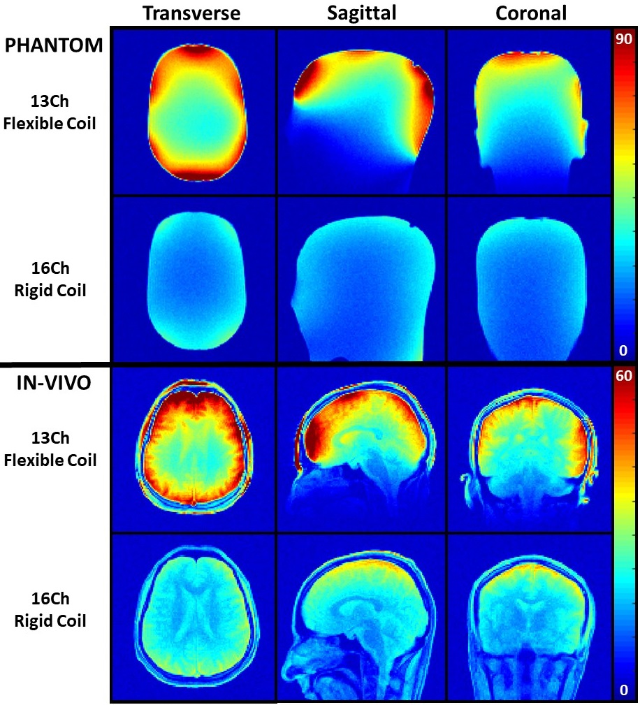
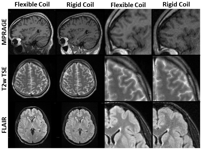
The quality factor ratios for a 12-cm loop separated by 0 and 4-cm from a conductive head phantom (27% polyvinylpyrrolidone, 0.44% salt)11 were 2.5 and 1.2 (Figure 2), resulting in a roughly 2-fold drop in efficiency and highlighting advantage of a close-fitting loop. For context, loops in the flexible coil were separated from the head phantom by 2.5-cm or less, whereas a lateral gap of roughly 4-cm was present between the phantom and rigid reference coil. The SNR maps in the phantom showed that the flexible coil provided approximately 60% advantage over the rigid reference coil in the center of the transverse slice (Figure 3). The SNR advantage in vivo was approximately 30-50% in the ventricles and over 2-fold in some peripheral regions. Improved quality can be observed in MPRAGE, T2w TSE, and FLAIR images acquired with the flexible coil, particularly in zoomed views of the cortex (Figure 4).Discussion
We attempted to maximize SNR in the brain at 0.55T by developing a 13-channel flexible coil. This work builds upon our prior finding that loops based on RG-223 cable or standard rigid copper provide nearly equivalent SNR9, indicating mechanical flexibility can be achieved without compromising baseline efficiency. To adapt RG-223 cable coils to head imaging, we arranged them with dodecahedral geometry that allowed neighbor decoupling while maximizing loading, which can be especially important at low frequencies such as 23.55MHz. In vivo experiments showed that the flexible coil provided approximately 30-50% SNR advantage in the ventricles over the rigid reference coil. We also observed substantial improvements in image quality; for example, cortical gray and white matter transitional regions are more clearly visualized in images acquired with the flexible coil. Notably, absent from MPRAGE, T2w TSE, and FLAIR images were signal hotspots that might be expected with a close-fitting coil. MPRAGE images showed acceptable coverage of the cerebellum, but additional loops may be required to extend coverage inferiorly. Flexible coils can provide significant loading and SNR advantages over rigid coils but have been applied primarily to musculoskeletal imaging and have been underdeveloped for the head. While the performance of the flexible head coil in this study is promising, several practical challenges could be addressed to make the coil user friendly. For example, although the dodecahedral geometry was set up to allow an unencumbered visual field, it is unclear whether patients will tolerate a coil that can make contact with the face. Further, we utilized a cloth balaclava to insulate the subject from the coil, which cannot be quickly sanitized for routine use. A sanitizable cover is likely to increase the gap between the coil and head, suggesting a slight compromise in SNR. Another issue is that the minimalist coil structure did not offer a convenient means to immobilize the head, which may be desired to suppress motion artifacts. Finally, a bench top trial on a mannequin indicated that the flexible coil can accommodate head sizes up to the 99th percentile12, but additional exams are needed to evaluate image quality, patient comfort, and SNR in a variety of heads. In conclusion, the prototype flexible coil demonstrated promising SNR and image quality in the brain, which may help illuminate aspects unique to 0.55T MRI such as low magnetic field inhomogeneity and specific absorption rate, and short spin relaxation times. However, the coil requires mechanical improvements for routine use.Acknowledgements
This work performed under the rubric of the Center for Advanced Imaging Innovation and Research (CAI2R; www.cai2r.net) at the New York University School of Medicine, which is an NIBIB Biomedical Technology Resource Center (NIH P41 EB017183). The authors acknowledge the assistance of Siemens Healthcare in the modification of the MRI system for operation at 0.55T under an existing research agreement between NYU and Siemens Healthcare.References
1. Siemens Healthineers Announces FDA Clearance of MAGNETOM Free.Max 80 cm
MR Scanner,
<https://www.siemens-healthineers.com/en-us/press-room/press-releases/fdaclearsmagnetomfreemax.html>
(2020).
2. 21 CFR Part 892. Magnetic Resonance Diagnostic Device,
<https://www.accessdata.fda.gov/cdrh_docs/pdf21/K210611.pdf> (2021).
3. Khodarahmi, I. et al. New-Generation Low-Field Magnetic Resonance Imaging of Hip
Arthroplasty Implants Using Slice Encoding for Metal Artifact Correction: First
In Vitro Experience at 0.55 T and Comparison With 1.5 T. Invest Radiol, doi:10.1097/RLI.0000000000000866 (2022).
4. Runge, V. M. & Heverhagen, J.
T. Advocating the Development of Next-Generation, Advanced-Design Low-Field
Magnetic Resonance Systems. Invest Radiol
55, 747-753,
doi:10.1097/RLI.0000000000000703 (2020).
5. Darnell, D., Truong, T. K. &
Song, A. W. Recent Advances in Radio-Frequency Coil Technologies: Flexible,
Wireless, and Integrated Coil Arrays. J
Magn Reson Imaging 55,
1026-1042, doi:10.1002/jmri.27865 (2022).
6. Duan, Y. et al. A 32-Ch Over-Overlapped Semi-Flexible RF Head Coil Array
with Improved Deep Brain SNR. ISMRM,
4498 (2022).
7. Duan, Y., Wang, J., Liu, F.,
Marsh, R. & Vaughan Jr, J. A Continuously Adjustable 32-Ch Head Coil Array
for MRI at 3T. ISMRM, 1592 (2021).
8. Adriany, G. et al. A geometrically adjustable 16-channel transmit/receive
transmission line array for improved RF efficiency and parallel imaging
performance at 7 Tesla. Magn Reson Med
59, 590-597, doi:10.1002/mrm.21488
(2008).
9. Wang, B. et al. A flexible MRI coil based on a cable conductor and applied
to knee imaging. Sci Rep 12, 15010, doi:10.1038/s41598-022-19282-6
(2022).
10. Wiggins, G. C. et al. A Close-Fitting 7 Tesla 8 Channel Transmit/Receive Helmet
Array with Dodecahedral Symmetry and B1 Variation Along Z ISMRM, 148 (2008).
11. Ianniello, C. et al. Synthesized tissue-equivalent dielectric phantoms using
salt and polyvinylpyrrolidone solutions. Magn
Reson Med 80, 413-419,
doi:10.1002/mrm.27005 (2018).
12. Tilley,
A. R. The measure of man and woman. (The Whitney Library of Design, 1993).
Figures