0306
Compact and Lightweight Single-sided Inward-outward (IO)-ring permanent magnet array for back imaging1Singapore University of Technology and Design, Singapore, Singapore, 2Zhejiang University, Hangzhou, China, 3Chiba University, Chiba, Japan
Synopsis
Keywords: Low-Field MRI, Low-Field MRI, back imaging
A compact and lightweight single-sided Inward-outward (IO)-ring permanent magnet array is proposed for back imaging. Its size is 1396×528×1080mm3 and it weighs 924 kg. Within a field-of-view (FoV) of 300×80×20mm3, it has an axial magnetic field with an average strength of 129.8mT, a built-in gradient (averaged at 158mT/m) that corresponds to a radiofrequency (RF) bandwidth of 9.7% and a good linearity with a R2-coefficient of 0.952. It has a compact 5-Gauss zone of 400×320×460mm3.Introduction
Permanent magnet array (PMA) designs are important for portable magnetic resonance imaging (MRI) for its portability. Aside from the popular Halbach array that provides transverse magnetic field for imaging, another type of PMA called inward-outward (IO)-ring shows strong field in the axial direction1. An IO-ring consists of a pair of permanent magnet rings with opposite radial polarizations, which can be either continuous or discretized2-4. An IO-ring usually shows a concentric field pattern. Variants of IO-rings were proposed, such as a combination of asymmetric IO-rings with different radii in the axial direction to produce axial gradients5. Asymmetry in the $$$\phi$$$-direction within a magnet ring was proposed to generate transverse gradients6. They are both close-bore (i.e., in-situ array7) and designed for head imaging. In this work, we design and optimize a single-sided IO-ring for back imaging, starting with a standard half IO-ring. It shows an average field strength of 129.8mT and a built-in gradient averaged at 158mT/m (inhomogeneity of 9.7%) with good linearity ($$$R^2$$$coefficient of 0.952) within a field-of-view (FoV) of 300×80×20mm3.Methods
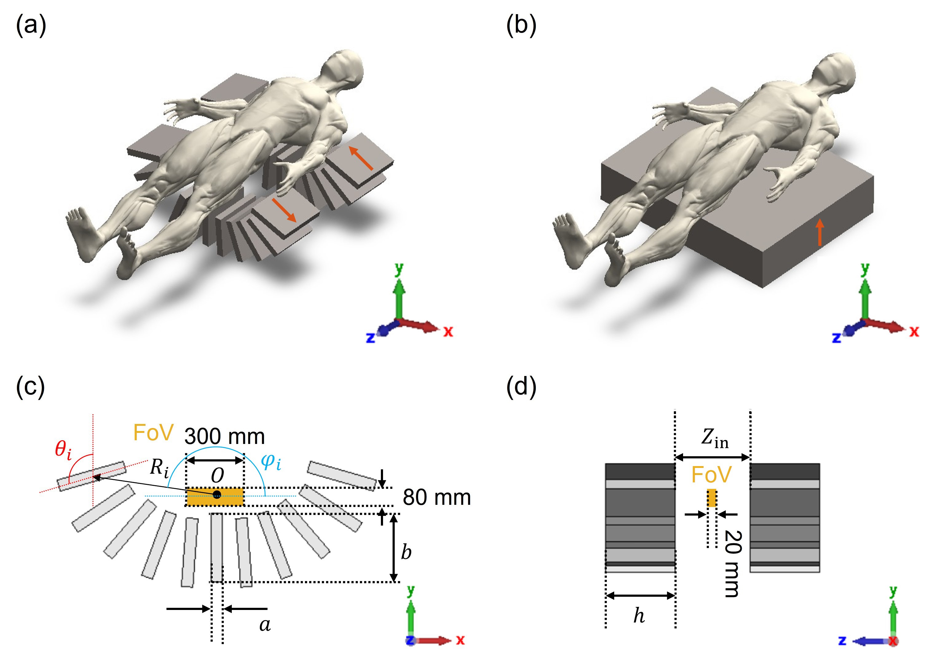
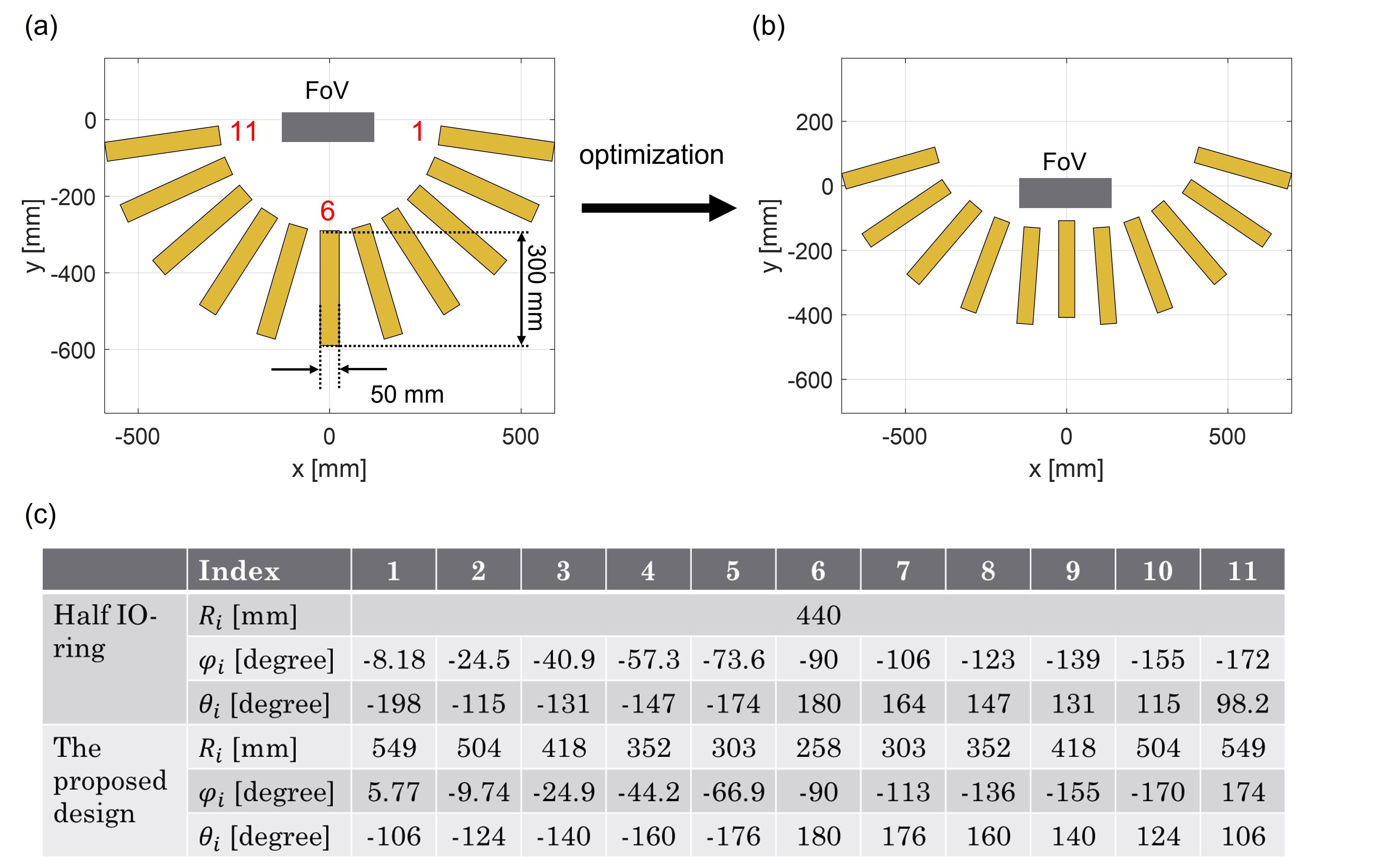
The overview of the proposed design shown in Fig.1(a) consists of two irregular half-rings with opposite radial magnetization. Its cross-sectional and side view are shown in Fig.1(c) and (d), respectively. The optimization was started with a half IO-ring consisting of magnet blocks as shown in Fig.2(a). The parameters under optimization are the dimension of the magnet block $$$(a,b,h)$$$, the radius $$$R_i$$$ from the z-axis, the location angle $$$\varphi_i$$$ around the origin, the orientation angle $$$\theta_i$$$ around the magnet center, and the inner distance $$$Z_\text{in}$$$ between the two rings. The design objectives are, 1)an average field strength>100mT, 2)a gradient within 10% and 3)a linearity with $$$R^2$$$-coefficient>0.95 within the FoV of 300×80×20mm3 as shown in Fig.1(c) and (d). All magnetic material is N52 NdFeB with a remanence of 1.43T for a high field strength.The initial values of $$$R_i$$$, $$$(a,b,h)$$$, and $$$Z_\text{in}$$$ are 440mm, (30,250,250)mm and 250mm, respectively, considering the size and weight constraints of the PMA which are 1.5×0.7×1.5m3 and 1ton. $$$R_i$$$ was varied in a range of [-200,200]mm while $$$\varphi_i$$$ and $$$\theta_i$$$ were varied in a range of [-30,30] degrees for more flexibility while maintaining high field strength and avoiding physical intersection. The other parameters, $$$a$$$, $$$b$$$, $$$h$$$, and $$$Z_\text{in}$$$, are fine-tuned within ±150mm. The magnetic field of a PMA was calculated by “MagTetris”, an in-house written calculator for permanent magnet blocks8. The design is compared to a +y-magnetized single-sided magnet (Fig.1(b)) of the same maximum physical dimensions.
Results & Discussions
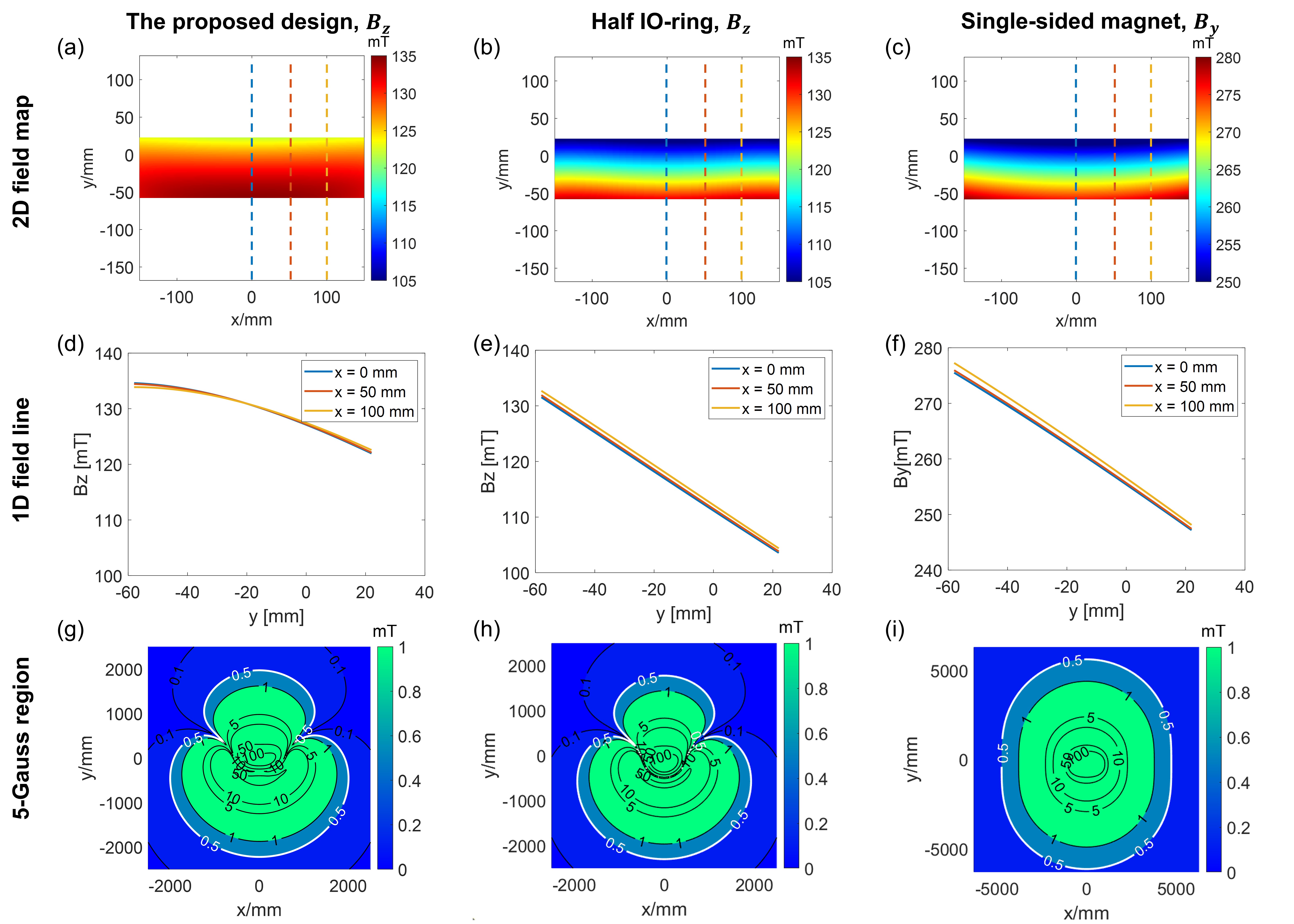
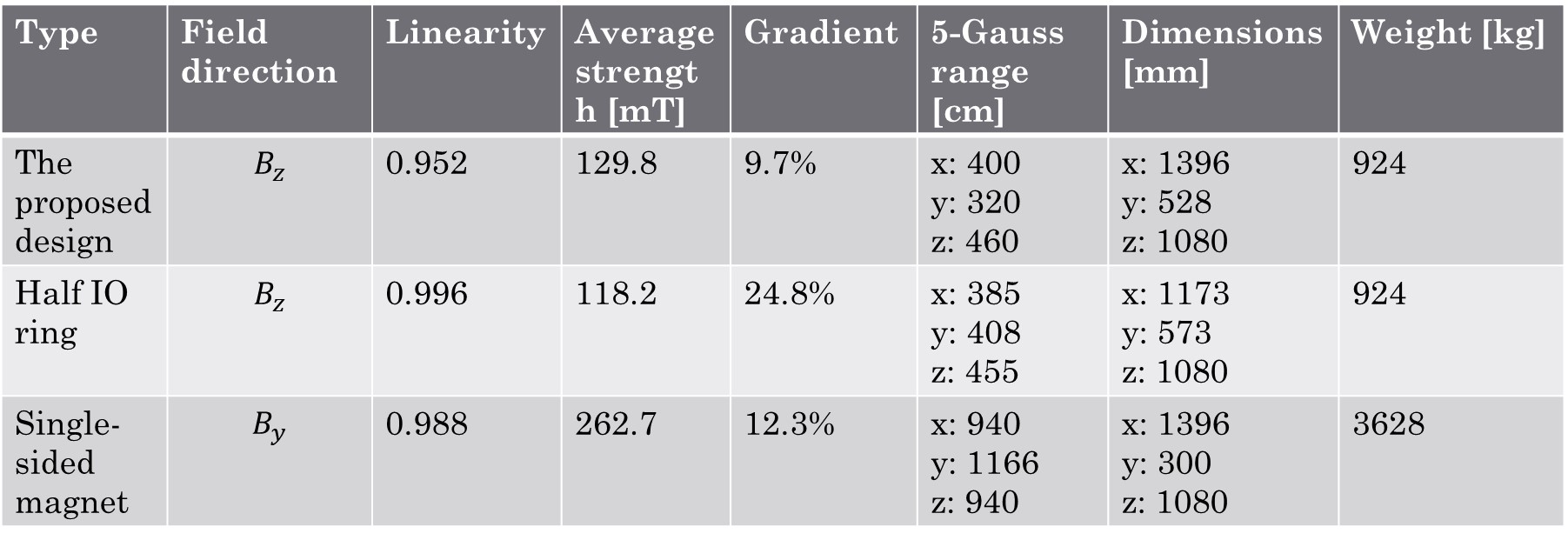
The optimized parameters are $$$(a,b,h)=(50,300,350)$$$mm and $$$Z_\text{in}=380$$$mm. The cross-sectional view of the optimized design is shown in Fig.2(b). Table-1 (Fig.2(c)) shows the resultant $$$R_i$$$’s, $$$\varphi_i$$$’s and $$$\theta_i$$$’s. The performances of the proposed design are compared to the half IO-ring and single-sided magnet in Fig.3.Column-1-3 in Fig.3 show the magnetic field at z=0 of the proposed design(Bz), half IO-ring(Bz), and the single-sided magnet(By). Row 1 shows the field patterns within the FoV, Row 2 shows the field plots along the highlighted vertical lines at x=0, 50, and 100mm, and Row-3 shows the 5-Gauss regions. As shown in Column-1, the proposed design generates a monotonic gradient, averaged at 158mT/m in the y-direction(corresponding to FoV≤300mm in the same direction at $$$\Delta t=0.5$$$μs), and the line plots show consistency of gradients along the x-direction. The 5-Gauss region is asymmetric with the smaller part above the patient. In Column-2 and -3, the half IO-ring and the single-sided magnet show gradients of 366.5mT/m and 403.9mT/m with linearity of 0.996 and 0.988, corresponding to inhomogeneity at 24.8% and 12.3%, respectively. Compared to the half IO-ring, the proposed design has a smaller gradient that can work with narrowband RF coils(<10%) without compromising the linearity. Compared to the single-sided magnet, it has a 5-Gauss region that is only 1/17 of that of the single-sided one, making it adaptable for more scenarios. A detailed comparison among the three are shown in Table-2(Fig.4). As shown in Table-2, the weight of the proposed design is only 1/4 of that of the single-sided magnet when having the same maximum physical dimensions.
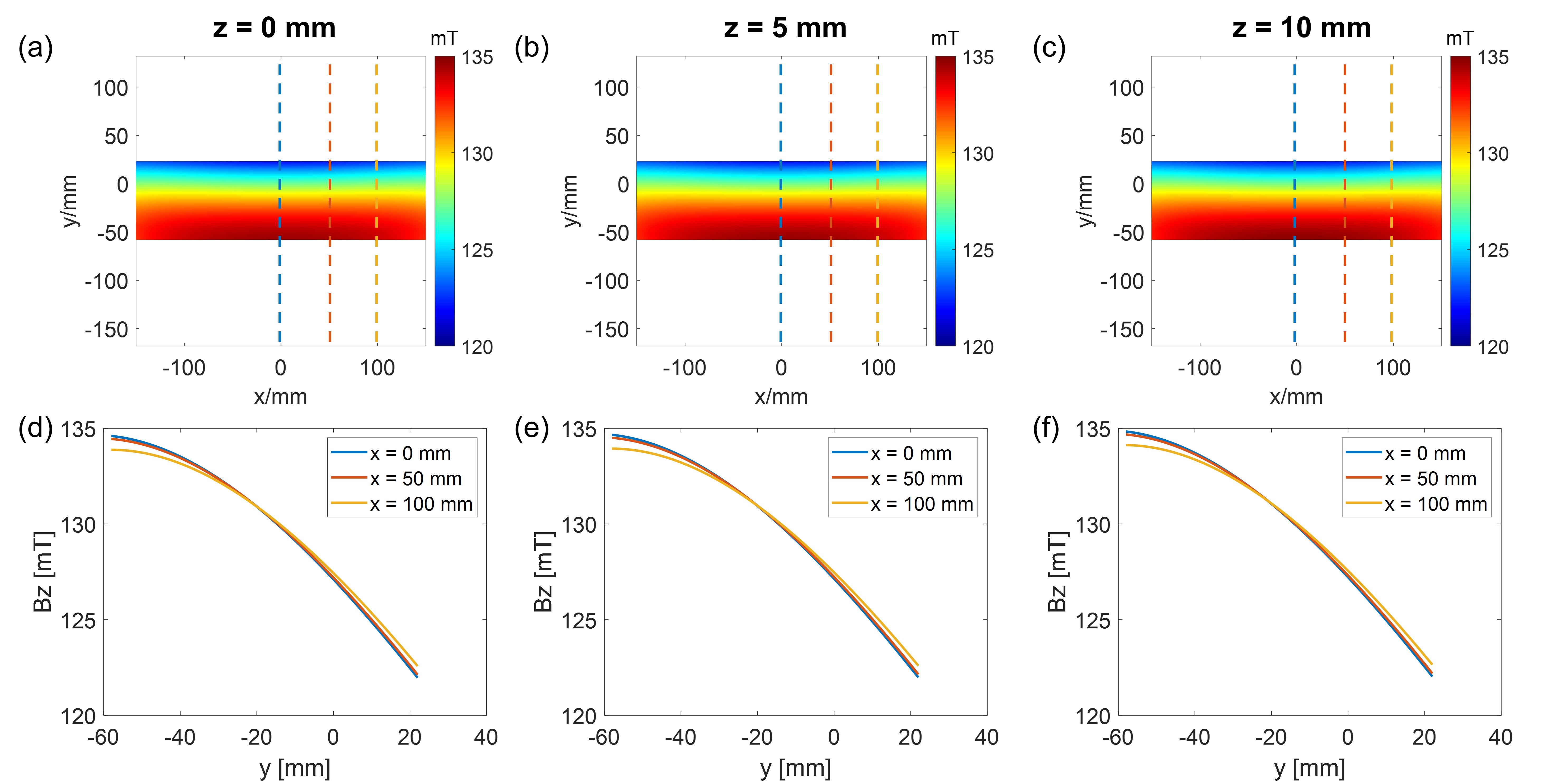
Fig.5 shows the Bz field of the proposed design on slices z=0, 5, and 10mm. The average field strengths are between 129.8mT to 129.9mT and the gradient increases from 158mT/m to 160.1mT/m. The field variance among the neighboring z-slices is negligible. To extend the FoV along the z-direction, more sub-magnet arrays are needed1.
Conclusion
In this abstract, we propose a compact and lightweight single-sided IO-ring PMA for back imaging. The proposed design has an average field strength of 129.8mT and an averaged gradient of 158mT/m with fair linearity on the central slice within an FoV of 300×80×20mm3. The gradient corresponds to FoV≤300mm in the same direction at $$$\Delta t=0.5$$$μs. The inhomogeneity from the gradient is controlled to 9.7% with only one pair of magnet rings, which is likely to work with practical RF coils. The proposed design demonstrates the potential of using single-sided IO-ring PMA for dedicated MRI. Further optimization can be done to enlarge the FoV (especially along the z-direction), and/or to increase the field strength and to improve the field linearity.Acknowledgements
No acknowledgement found.References
1. Ting-Ou Liang, Yan Hao Koh, Tie Qiu, Erping Li, Wenwei Yu, Shao Ying Huang, High-Performance Permanent Magnet Array Design by a Fast Genetic Algorithm (GA)-based Optimization for Low-Field Portable MRI, Journal of Magnetic Resonance, 2022, 107309, ISSN 1090-7807, https://doi.org/10.1016/j.jmr.2022.107309.
2. G. Aubert, “Permanent magnet for nuclear magnetic resonance imaging equipment,” July 26, 1994. US Patent 5,332,971
3. G. Miyajima, Cylindrical permanent magnet apparatus, Japanese Patent JPS60210804A (Oct.23, formally Apr. 4, 1984 1985).
4. E. Nishino, Magnetic medical appliance, UK Patent, GB2112645A (Jul.27 1983).
5. Z. H. Ren, W. C. Mu and S. Y. Huang, "Design and Optimization of a Ring-Pair Permanent Magnet Array for Head Imaging in a Low-Field Portable MRI System," in IEEE Transactions on Magnetics, vol. 55, no. 1, pp. 1-8, Jan. 2019, Art no. 5100108, doi: 10.1109/TMAG.2018.2876679.
6. Z. H. Ren, J. Gong and S. Y. Huang, "An Irregular-Shaped Inward-Outward Ring-Pair Magnet Array With a Monotonic Field Gradient for 2D Head Imaging in Low-Field Portable MRI," in IEEE Access, vol. 7, pp. 48715-48724, 2019, doi: 10.1109/ACCESS.2019.2909834.
7. Huang S, Ren ZH, Obruchkov S, Gong J, Dykstra R, Yu W. Portable Low-Cost MRI System Based on Permanent Magnets/Magnet Arrays. Investig Magn Reson Imaging. 2019 Sep;23(3):179-201. https://doi.org/10.13104/imri.2019.23.3.179
8. Tingou Liang, Tie Qiu, and Shaoying Huang, A Simulator, “MagTetris”, for Fast Calculation of Magnetic Field and Force for Permanent Magnets, ISMRM (2022).
Figures