0301
Cerebral Time-of-flight Magnetic Resonance Angiography at Ultra-low-field: A Preliminary Study at 0.055 Tesla1Laboratory of Biomedical Imaging and Signal Processing, the University of Hong Kong, Hong Kong, China, 2Department of Electrical and Electronic Engineering, the University of Hong Kong, Hong Kong, China
Synopsis
Keywords: Low-Field MRI, Brain
Recent development of ultra-low-field (ULF) MRI presents opportunities for low-cost and portable brain imaging in point-of-care scenarios or/and low- and mid-income countries. Magnetic resonance angiography (MRA) is an essential part of MR neuroimaging protocols especially for stroke assessment, yet its feasibility at ULF remains unknown. In this study, we explore the time-of-flight MRA at 0.055 Tesla. We demonstrate cerebral MRA using flow-compensated gradient echo sequences, enabling visualization of main cerebral arteries and veins. We envision that usable and quality brain MRA can be potentially achieved at ULF with further sequence/reconstruction optimization and use of intravascular contrast agent.Introduction
Magnetic resonance angiography (MRA), including the inflow time-of-flight (TOF) technique1,2, has proven to be valuable in the diagnosis of cerebral vascular diseases and brain injuries3-5. Recent development of ultra-low-field (ULF) MRI presents tremendous opportunities for low-cost and portable brain imaging in point-of-care scenarios or/and low- and mid-income countries6-12. MRA is an essential part of MR neuroimaging protocols especially for early assessment of acute stroke, yet its feasibility at ULF remains unknown. In this study, we explore TOF MRA on a low-cost and shielding-free 0.055 Tesla brain MRI platform that we developed recently6.Method
In vivo experimentsAll in vivo experiments were conducted on a permanent magnet based 0.055 Tesla head MRI scanner with a self transmit/receive head coil6. The scanner was compact and free from any magnetic and RF shielding. Normal subjects were enrolled in this study under an institutional review board approval. Written informed consent was obtained from each subject prior to the study.
3D and 2D GRE sequences were implemented to visualize arteries and cerebral veins, respectively. To reduce the signal loss due to flowing blood spin dephasing, the first-order flow compensation was applied in all three directions.
For artery imaging, a ramped or TONE excitation RF pulse with flip angle increasing from 35° to 70° in foot to head direction was implemented in 3D GRE sequence for each multi-slice 3D slab acquisition. Sequence parameters were TR/TE = 27/8.9ms, 75% partial echo, BW = 10kHz, acquisition resolution = 2×2×2mm3, matrix size = 108×108×16, slab thickness = 32mm, and NEX = 8. Three overlapping slabs were acquired sequentially along foot to head direction with 8mm slab overlap. Total acquisition time was 18.7 mins.
For vein imaging, 2D slices were sequentially acquired obliquely along head to foot direction using a single-slice GRE sequence with TR/TE = 28/9.7ms, flip angle = 90°, 75% partial echo, BW = 10kHz, acquisition in-plane resolution = 2×2mm2, acquisition matrix size = 108×108, slice thickness = 4mm with zero gap, 32 slices, NEX = 8, and total acquisition time = 12.9 mins.
Image reconstruction and processing
K-space data were first processed for electromagnetic interference (EMI) signal removal by utilizing the EMI sensing coil signals6, and then 2× zero-padded before imaging reconstruction, resulting in a display resolution of 1×1×1mm3 and 1×1×2mm3 for cerebral artery and vein images, respectively. Manual cut-out of high intensity scalp fat tissues and some muscle tissues was performed before maximum intensity projection (MIP).
Results
Vessel-to-background contrast was achieved by multi-slab 3D TOF MRA. As shown in Fig. 1, the main cerebral arteries, including the internal carotid artery (red arrows), basilar artery (yellow arrows) and middle cerebral artery (blue arrows), were clearly visible in the raw 2D images. Fig. 2 shows the MIP images in three directions. In general, they enabled the visualization of main arterial branches. However, they were sometimes not smooth or incomplete, especially in regions between neighboring slabs. This likely arose from the lack of optimization in slab or flip angle profile, overlapping, and post-processing such as intensity homogenization before MIP. Fig. 3 and Fig. 4 show the raw vein imaging and MIP results, respectively. Here 2D GRE with a large flip angle and short TR effectively suppressed the background signal and enhanced the large veins through a strong inflow effect. Right/left sigmoid sinus (Fig. 3a and Fig. 4b, red arrows), right/left transverse sinus (Fig. 3b and Fig. 4c, yellow arrows) and superior sagittal sinus (Fig. 3c and Fig. 4d, blue arrows) could be readily identified and visualized. Note that the part of the superior sagittal and right/left transverse sinus were hypo-intense in the MIP images due to the in-plane saturation of the slow flowing venous blood (Fig. 4b-d, white arrows).Discussion and Conclusions
Cerebral MRA is a key protocol in neuroimaging, especially for early acute stroke assessment. In this preliminary study, we demonstrate the possibility of non-contrast cerebral TOF MRA at ULF for the first time. Main arteries and veins could be visualized at 0.055 Tesla. The preliminary results clearly indicated the potential of ULF MRI for MRA despite the low SNR. Although not demonstrated, we expect that neck carotid vessels can be readily visualized at ULF due to their large sizes and strong inflow effect.To improve ULF MRA for visualizing small cerebral vessels with higher resolution and stronger contrasts, we envision the following steps in future development: (i) sequence and post-processing optimization for slab or flip angle profile, short TE, less in-plane flow saturation, selective suppression of venous or arterial flow through pre-saturation, slab overlapping and MIP visualization; (ii) strong magnetization transfer preparation to suppress stationary gray/white matter and muscle tissues, especially given the extremely low RF SAR at ULF; (iii) use of compressed sensing acquisition and reconstruction to reduce scan time, increase the spatial resolution, or/and suppress noise; and (iv) use of intravascular blood pool contrast agent to shorten blood T1, thus further enhancing blood signals. Such strategies may also advance the use of ULF MRI for abdominal and peripheral vessel imaging in the future.
Acknowledgements
This work was supported in part by Hong Kong Research Grant Council (R7003-19F, HKU17112120, HKU17127121 and HKU17127022 to E.X.W., and HKU17103819, HKU17104020 and HKU17127021 to A.T.L.L.), Lam Woo Foundation, and Guangdong Key Technologies for AD Diagnostic and Treatment of Brain (2018B030336001) to E.X.W..References
[1] Alfidi RJ, Masaryk TJ, Haacke EM, Lenz GW, Ross JS, Modic MT, Nelson AD, LiPuma JP, Cohen AM. MR angiography of peripheral, carotid, and coronary arteries. AJR Am J Roentgenol 1987;149(6):1097-1109.
[2] Laub GA. Time-of-flight method of MR angiography. Magn Reson Imaging Clin N Am 1995;3(3):391-398.
[3] Cirillo M, Scomazzoni F, Cirillo L, Cadioli M, Simionato F, Iadanza A, Kirchin M, Righi C, Anzalone N. Comparison of 3D TOF-MRA and 3D CE-MRA at 3T for imaging of intracranial aneurysms. Eur J Radiol 2013;82(12):e853-859.
[4] Boujan T, Neuberger U, Pfaff J, Nagel S, Herweh C, Bendszus M, Möhlenbruch MA. Value of Contrast-Enhanced MRA versus Time-of-Flight MRA in Acute Ischemic Stroke MRI. AJNR Am J Neuroradiol 2018;39(9):1710-1716.
[5] Edelman RR, Koktzoglou I. Noncontrast MR angiography: An update. J Magn Reson Imaging 2019;49(2):355-373.
[6] Liu Y, Leong ATL, Zhao Y, Xiao L, Mak HKF, Tsang ACO, Lau GKK, Leung GKK, Wu EX. A low-cost and shielding-free ultra-low-field brain MRI scanner. Nat Commun 2021;12(1):7238.
[7] Yuen MM, Prabhat AM, Mazurek MH, Chavva IR, Crawford A, Cahn BA, Beekman R, Kim JA, Gobeske KT, Petersen NH, Falcone GJ, Gilmore EJ, Hwang DY, Jasne AS, Amin H, Sharma R, Matouk C, Ward A, Schindler J, Sansing L, de Havenon A, Aydin A, Wira C, Sze G, Rosen MS, Kimberly WT, Sheth KN. Portable, low-field magnetic resonance imaging enables highly accessible and dynamic bedside evaluation of ischemic stroke. Sci Adv 2022;8(16):eabm3952.
[8] He Y, He W, Tan L, Chen F, Meng F, Feng H, Xu Z. Use of 2.1 MHz MRI scanner for brain imaging and its preliminary results in stroke. J Magn Reson 2020;319:106829.
[9] O'Reilly T, Teeuwisse WM, de Gans D, Koolstra K, Webb AG. In vivo 3D brain and extremity MRI at 50 mT using a permanent magnet Halbach array. Magn Reson Med 2021;85(1):495-505.
[10] Mazurek MH, Cahn BA, Yuen MM, Prabhat AM, Chavva IR, Shah JT, Crawford AL, Welch EB, Rothberg J, Sacolick L, Poole M, Wira C, Matouk CC, Ward A, Timario N, Leasure A, Beekman R, Peng TJ, Witsch J, Antonios JP, Falcone GJ, Gobeske KT, Petersen N, Schindler J, Sansing L, Gilmore EJ, Hwang DY, Kim JA, Malhotra A, Sze G, Rosen MS, Kimberly WT, Sheth KN. Portable, bedside, low-field magnetic resonance imaging for evaluation of intracerebral hemorrhage. Nat Commun 2021;12(1):5119.
[11] Sheth KN, Mazurek MH, Yuen MM, Cahn BA, Shah JT, Ward A, Kim JA, Gilmore EJ, Falcone GJ, Petersen N, Gobeske KT, Kaddouh F, Hwang DY, Schindler J, Sansing L, Matouk C, Rothberg J, Sze G, Siner J, Rosen MS, Spudich S, Kimberly WT. Assessment of Brain Injury Using Portable, Low-Field Magnetic Resonance Imaging at the Bedside of Critically Ill Patients. JAMA Neurol 2020;78(1):41-47.
[12] Cooley CZ, McDaniel PC, Stockmann JP, Srinivas SA, Cauley SF, Śliwiak M, Sappo CR, Vaughn CF, Guerin B, Rosen MS, Lev MH, Wald LL. A portable scanner for magnetic resonance imaging of the brain. Nat Biomed Eng 2021;5(3):229-239.
Figures
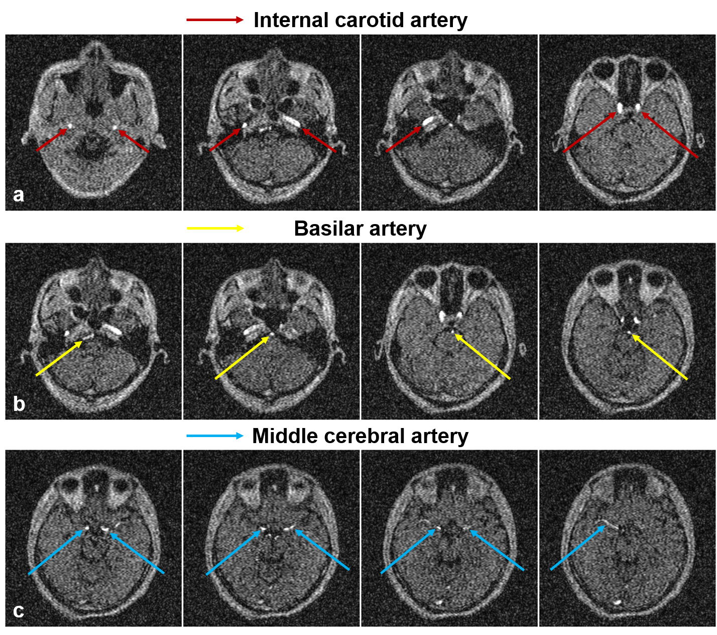
Figure 1. Representative axial images from flow-compensated multi-slab 3D GRE acquisition at 0.055 Tesla. Strong vessel-to-background contrast could be obtained through effective background saturation using short TR and ramped RF excitation flip angle profile. The main cerebral arteries, including the internal carotid artery (Fig. 1a, red arrows), basilar artery (Fig. 1b, yellow arrows) and middle cerebral artery (Fig. 1c, blue arrows), could be observed.
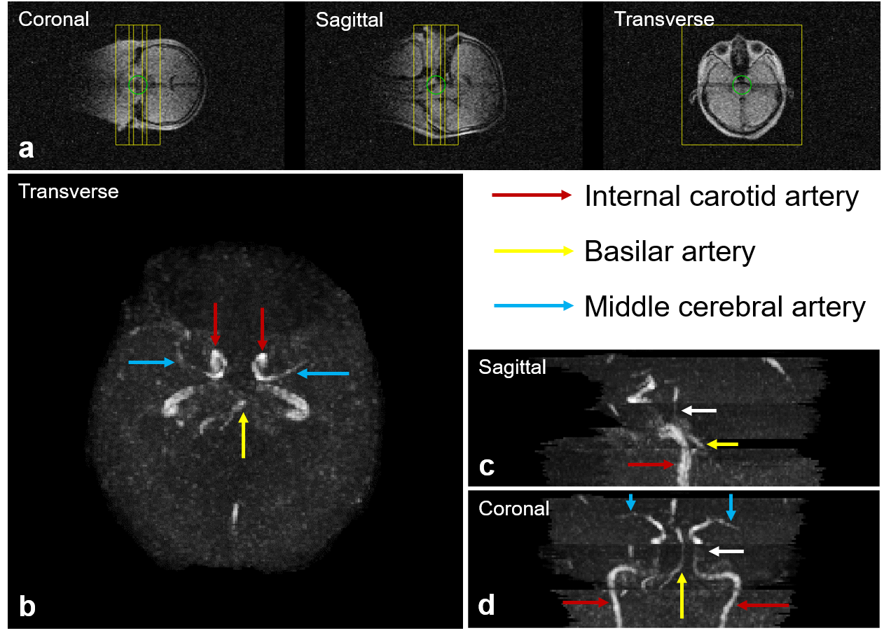
Figure 2. Maximum intensity projections (MIPs) of cerebral arteries in transverse, sagittal and coronal views at 0.055 Tesla. (a) The location and orientation of three overlapping 3D slabs. The internal carotid artery (red arrows), basilar artery (yellow arrows) and middle cerebral artery (blue arrows) were observed to be complete and well connected, and their morphology could be well perceived from the MIPs. Note that, due to the reduced inflow effect and increased saturation at the exiting side of each slab, vessel visibility decreased (white arrows in c & d).
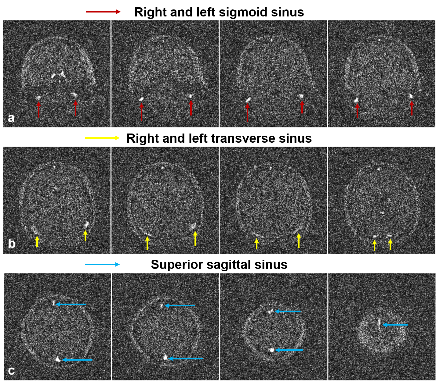
Figure 3. Representative images from 2D flow-compensated TOF GRE acquisition at 0.055 Tesla. The background was mostly suppressed with large flip angle and short TR, allowing the right/left sigmoid sinus (red arrows), right/left transverse sinus (yellow arrows) and superior sagittal sinus (blue arrows) to be clearly visible.
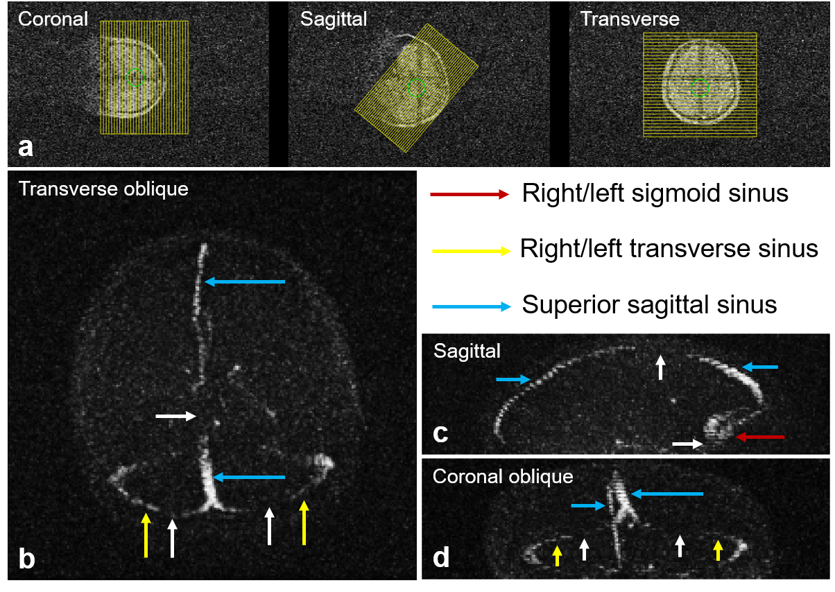
Figure 4. MIPs of cerebral veins in transverse oblique, sagittal and coronal oblique views. The morphology of right/left sigmoid sinus (red arrows), right/left transverse sinus (yellow arrows) and superior sagittal sinus (blue arrows) could be visualized. Note that, due to low flow velocity and in-plane flow saturation, some parts of the vessels became invisible (white arrows).