0218
A Metamaterial Liner Body Coil for Wide-bore 3T MRI1Oncology, Medical Physics, University of Alberta, Edmonton, AB, Canada, 2GE Healthcare, Aurora, OH, United States, 3Electrical and Computer Engineering, University of Alberta, Edmonton, AB, Canada
Synopsis
Keywords: Hybrid & Novel Systems Technology, Body, metamaterial
The transmit field suffers from standing wave inhomogeneities at field strengths ≥3T, which degrade image quality and create specific absorption rate (SAR) hotspots. We present the first experimental demonstration of a whole-body metamaterial liner (metaliner) that enables traveling wave excitation at a lower frequency than achievable otherwise. The simulated transmit efficiencies for a comparable birdcage and metaliner were 2.43μT⁄√kW±23.8% and 1.80μT⁄√kW±25.5% respectively, and the maximum 10g local SAR was reduced by 18% with the metaliner. This shows that the metaliner is an attractive alternative to the BC with greater safety thanks to the lower localized SAR.
Introduction
At higher field strengths (e.g., ≥3T), the MR excitation becomes inhomogeneous due to standing wave effects arising from the inverse relationship between B0 and RF wavelength in the body1. Beyond concealing areas of disease, many MRI methods involve quantitative and dynamic studies of the MR signal dependent on a consistent excitation throughout the field of view2. Furthermore, the birdcage coil (BC) produces localized hot spots of the specific absorption rate (SAR). Imaging parameters that affect SAR become greatly constrained at 3T by safety limits3, limiting the contrast and SNR obtained. Thus, many clinical MRI applications are more effective at <3T, which nonetheless has worse signal-to-noise, spectroscopic resolution and imaging speed. Traveling wave (TW)-MRI was proposed to eliminate the BC using the conductive lining of the bore to produce the RF magnetic field with electromagnetic waveguide concepts4. The more homogeneously distributed electrical and magnetic fields were expected to mitigate SAR challenges. The use of MTMs as thin MRI bore liners to artificially lower the cutoff frequency was proposed in Ref. (5), following studies showing their utility for circular electromagnetic waveguides6–8. Since then, the MRI MTM-liner concept has been rigorously validated numerically9 and a robust analytical design framework has been developed10,11. The benefit of reduced SAR in human body models compared to the BC was demonstrated12. Here we investigate the real-world performance of a metaliner constructed for 3T imaging in a wide-bore magnet (70cm diameter) to determine its feasibility as an alternative to the stalwart BC.Methods
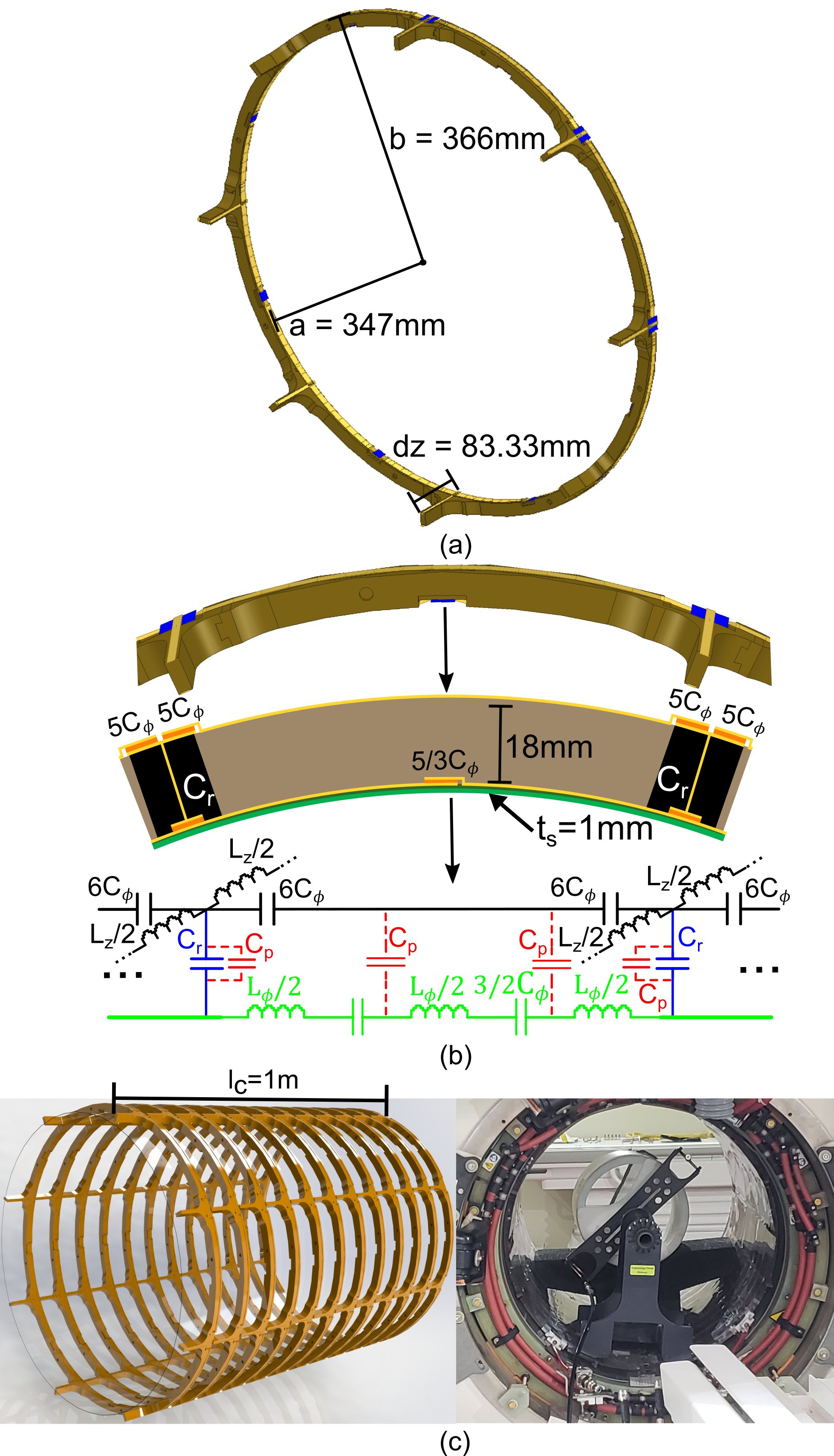
The geometry, the equivalent circuit of a single unit-cell, a rendering of the full 12 metaliner rings and photo of the constructed metaliner with temporary shield used to emulate the gradient shield are shown in Figure 1. The lumped capacitors are formed from overlapping conductors on Rogers 3003 substrate (Results and Discussion
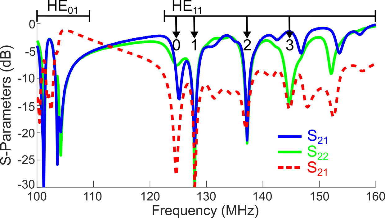
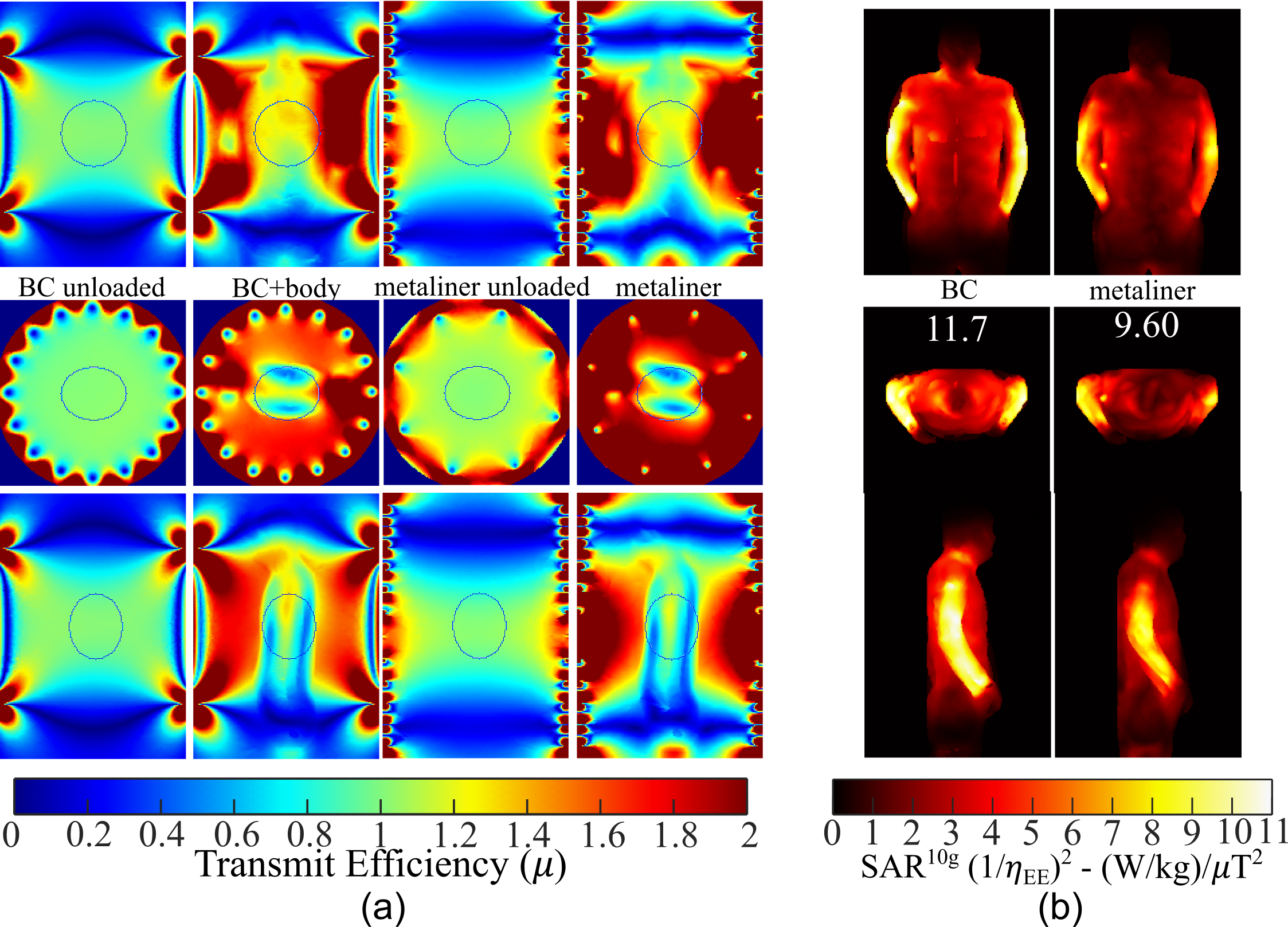
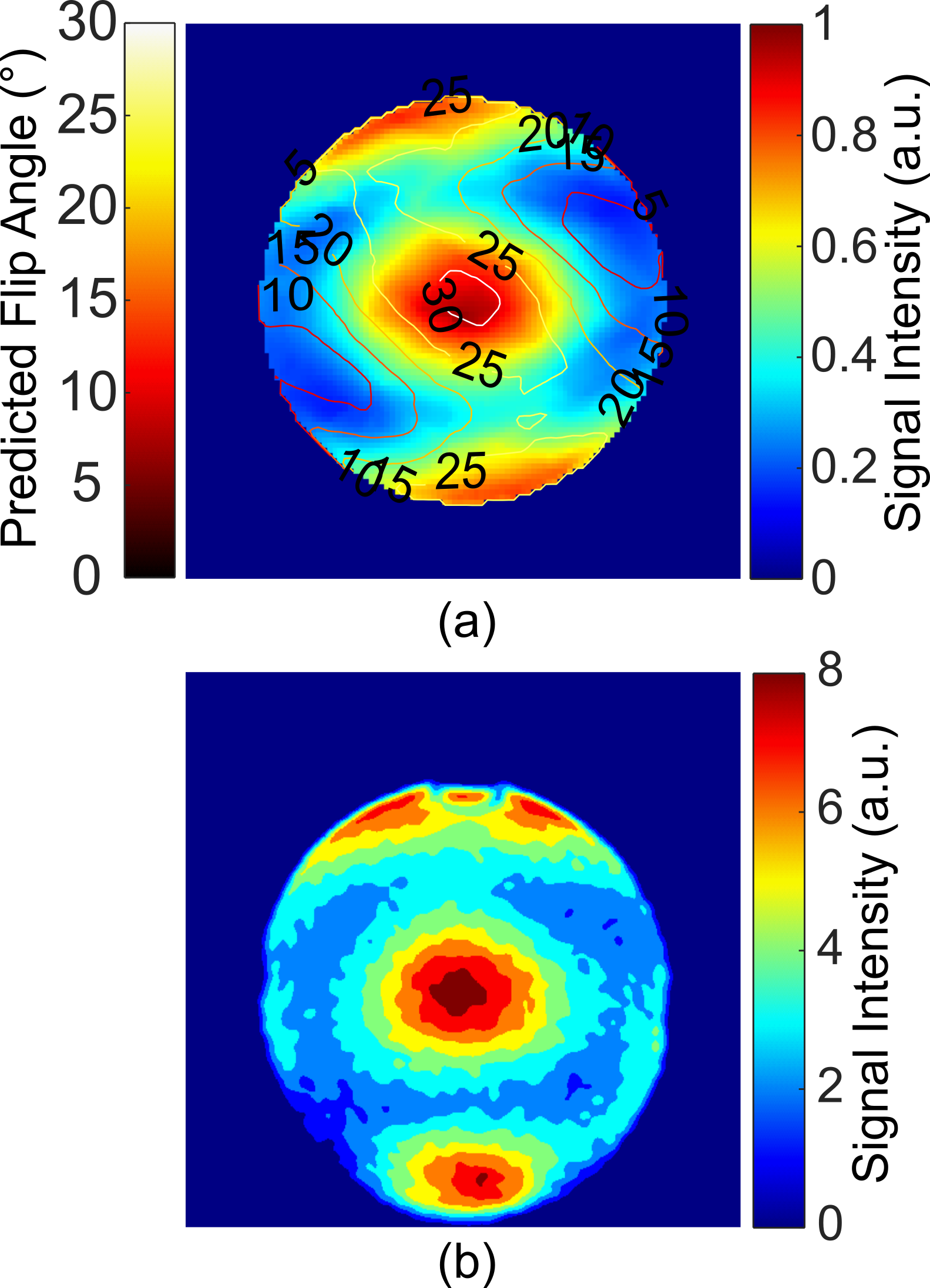
The scattering parameters for the loaded metaliner with temporary shield are shown in Figure 3, demonstrating that the ports are decoupled and matched. The simulated and measured transmission efficiency maps in orthogonal slices are shown in Figure 4a for the BC and metaliner. Within the ellipsoidal region of interest (12.5cm×10cm×12.5cm radii) the mean simulated transmit efficiencies were: BC unloaded - 5.74Conclusion
We have performed the first experimental demonstration of a metaliner used as a body coil for wide-bore MRI at 3T. Images match the simulations, which show the important benefit of reduced local SAR hot spots compared to the birdcage coil.Acknowledgements
This work was supported by the Alberta Innovates postdoctoral fellowship in health innovation, the Office of the Provost and VP of the University of Alberta, the University of Alberta Undergraduate Researcher Stipend, and the Natural Sciences and Engineering Research Council (NSERC) of Canada Discovery Grants program. We thank CMC Microsystems for software access and support by the University of Alberta Faculty of Engineering IT. We thank GE Healthcare for technical support including Lalit Rai, Ravi Jaiswal, David Lee and Dan Spence. Thanks to Rudi Kopp and Al Dean Davis (GE Healthcare) for measurement support.References
1. Ladd ME, Bachert P, Meyerspeer M, et al. Pros and cons of ultra-high-field MRI/MRS for human application. Prog Nucl Magn Reson Spectrosc. 2018;109:1-50. doi:10.1016/j.pnmrs.2018.06.001
2. Quantitative and qualitative comparison of 1.5 and 3.0 Tesla MRI in patients with chronic liver diseases J Magn Reson Imaging. 2009 Apr;29(4):869-79. doi: 10.1002/jmri.21719.
3. International Electrotechnical Commission., Particular Requirements for the Basic Safety and Essential Performance of Magnetic Resonance Equipment for Medical Diagnosis. (3rd Ed.). 3rd ed. IEC 60601–2‐33; 2010. Accessed March 6, 2022.
4. Brunner DO, De Zanche N, Frohlich J, Paska J, Pruessmann KP. Travelling-wave nuclear magnetic resonance. Nature. 2009;457(7232):994-998. doi:10.1038/nature07752
5. Pollock J, De Zanche N, Iyer A. Traveling-Wave MRI at Lower B0 Field Strengths Using Metamaterial Liners. Proc Intl Soc Mag Reson Med. 2012;20(Journal Article):2792.
6. Pollock JG, Iyer AK. Experimental Verification of Below-Cutoff Propagation in Miniaturized Circular Waveguides Using Anisotropic ENNZ Metamaterial Liners. IEEE Transactions on Microwave Theory and Techniques. 2016;64(4):1297-1305. doi:10.1109/TMTT.2016.2532872
7. Pollock JG, Iyer AK. Miniaturized Circular-Waveguide Probe Antennas Using Metamaterial Liners. IEEE Transactions on Antennas and Propagation. 2015;63(1):428-433. doi:10.1109/TAP.2014.2367551
8. Pollock JG, Iyer AK. Below-Cutoff Propagation in Metamaterial-Lined Circular Waveguides. IEEE Transactions on Microwave Theory and Techniques. 2013;61(9):3169-3178. doi:10.1109/TMTT.2013.2274780
9. Maunder A, Zanche ND, Iyer AK. Simulation Comparison of Birdcage Coil and Metamaterial Liner for MRI at 3T and 4.7T. In: 2020 50th European Microwave Conference (EuMC). ; 2021:1067-1070. doi:10.23919/EuMC48046.2021.9338226
10. Maunder AM, Barker C, De Zanche N, Iyer AK. Metamaterial Liner for MRI Excitation—Part 1: Theory, Modeling and Design. IEEE Access. 2022;10:41664-41677. doi:10.1109/ACCESS.2022.3167432
11. Maunder AM, Iyer AK, De Zanche N. Metamaterial Liner for MRI Excitation—Part 2: Design and Performance at 4.7T. IEEE Access. 2022;10:41678-41692. doi:10.1109/ACCESS.2022.3167764
12. Maunder A, Iyer AK, De Zanche N. Whole-body Metamaterial Liner RF Coil for 1H at 4.7 T with Reduced SAR Compared to Birdcage Coil. Proc Intl Soc Mag Reson Med. 2021;29:0183.
13. Yanamadala J, Noetscher GM, Rathi VK, et al. New VHP-Female v. 2.0 full-body computational phantom and its performance metrics using FEM simulator ANSYS HFSS. Annu Int Conf IEEE Eng Med Biol Soc. 2015;2015:3237-3241. doi:10.1109/EMBC.2015.7319082
14. Makarov SN, Noetscher GM, Nazarian A. Low-Frequency Electromagnetic Modeling for Electrical and Biological Systems Using MATLAB. Wiley; 2015.
Figures