0216
Degenerate Birdcage Coil Mixed with Bent Dipole Antennas to Enhance Central SNR in Phosphorus MRI/MRS of Human Brain at 7T
Daniel Wenz1,2, Thomas Dardano1,2, Mark Widmaier1,3, Songi Lim1,2, Zhiwei Huang1,2, and Lijing Xin1,2
1CIBM Center for Biomedical Imaging, Lausanne, Switzerland, 2Animal Imaging and Technology, Ecole Polytechnique Federale de Lausanne (EPFL), Lausanne, Switzerland, 3Laboratory of functional and metabolic imaging, Ecole Polytechnique Federale de Lausanne (EPFL), Lausanne, Switzerland
1CIBM Center for Biomedical Imaging, Lausanne, Switzerland, 2Animal Imaging and Technology, Ecole Polytechnique Federale de Lausanne (EPFL), Lausanne, Switzerland, 3Laboratory of functional and metabolic imaging, Ecole Polytechnique Federale de Lausanne (EPFL), Lausanne, Switzerland
Synopsis
Keywords: RF Arrays & Systems, RF Arrays & Systems
Dipole antennas can be combined with loop elements to increase a central SNR in human brain MRI at 7T (300MHz). However, this approach was not investigated at lower frequencies. In this study a degenerate birdcage coil was combined with a pair of bent dipole antennas to increase a central SNR for phosphorus MRS of human brain at 7T (120MHz). Simulations showed that this approach could provide a 1.6-fold central SNR gain vs. degenerate birdcage-only. The RF coil was constructed and successfully tested at the bench. In the next step, an experimental validation of the proposed strategy will be performed.Introduction
Phosphorus (31P) MRI/MRS is a powerful tool to probe brain metabolism and physiology in vivo1. So far most studies focused on the investigation of cortical areas. However, subcortical brain areas (e.g. basal ganglia, nucleus accumbens, thalamus, etc.) play essential roles in the regulation of a diversity of behaviors and cognition, and their dysfunction is implicated in several neurological and psychiatric disorders. Therefore, applying 31P MR studies in subcortical areas is of great interest. Despite using ultrahigh (UHF) magnetic field strengths, signal-to-noise-ratio (SNR) in subcortical regions (central region of the human brain) is still unsatisfactory. Unlike for peripheral regions, the SNR in the center of the brain is not expected to be improved by increasing the number of loop elements in the array2. However, recent work showed that combining loop elements with dipole antennas can be used to improve SNR in the center of human brain at UHF (300 MHz)3. To the best of authors’ knowledge, so far this strategy was not investigated at 120 MHz. This can be more challenging due to the size of a dipole antenna at lower frequency and not as strong coil-sample coupling than as at 300 MHz. Notwithstanding a lacking experimental evidence, we decided to pursue this idea inspired by a theoretical model provided by Lattanzi et al.4 Therefore, the goal of this work was to develop a degenerate birdcage coil mixed with bent dipole antennas for 31P MRI/MRS of human brain at 7T which could provide a central SNR increase.Methods
An 8-channel degenerate birdcage with 240 mm diameter for 120.3 MHz was designed similarly as reported earlier5. The length of each loop was 220 mm with 8 capacitors per loop. The copper width was 10 mm. Two large dipole antennas surrounding an average human head were incorporated into the birdcage design (Fig.1). Due to the significant length of the dipole antennas at 120.3 MHz (1.2m), they were bent and crossed, as demonstrated by Hong et al.6 This eliminated dipole-dipole coupling and enabled using smaller inductors for tuning. In our approach dipole antennas were intended to be used as receive-only elements. The RF feeds for 31P dipole antennas were located at the top of the head. The array was loaded with a spherical phantom (radius=85mm, εr=78, σ=0.4S/m). A 4-channel 1H dipole antenna array for anatomical imaging and B0 shimming was incorporated into the design. Each 1H RF feed point overlapped with the center of the corresponding 31P loop. The 31P RF coil was equipped with a 1:8 power divider and 8 transmit/receive switches (MRCoilTech,UK). Simulations were performed using Sim4Life (Zurich Medtech,Switzerland). Transmit field efficiency was defined as B1+/√P, where P is the input power. SNR was evaluated using an implementation of the Roemer’s algorithm7 which was based on the S-matrix formalism proposed earlier8. The same multi-channel simulation was used to investigate three scenarios: a) degenerate birdcage and dipole antennas on resonance, b) degenerate birdcage on resonance and dipole antennas open at feeding points, c) “standalone” degenerate birdcage coil (i.e. all ports in each dipole antenna defined as open making the antenna segments short). The combined 31P/1H array was constructed and evaluated (tuning, matching, decoupling) at the bench (Fig.2). Bench measurements were performed when the RF coil was placed inside a dummy head gradient insert.Results
S-matrix was obtained from simulations (Fig.3): coupling between adjacent loop elements below -15dB (loop-loop) and close to -10dB (up to -15dB) for non-adjacent ones. Coupling between 31P dipole antennas was below -40dB, and between dipole antennas and adjacent loop elements was close to -10dB. B1+ efficiency in the center of a spherical phantom was found to be 1.70 μT/√W (when 31P dipole antennas were open in TX) and 1.69 μT/√W for a “standalone” degenerate birdcage (Fig.4). SNR in the center of a spherical phantom calculated for a combination of degenerate birdcage and bent dipole antennas was the highest (Fig.5): it was approximately 1.6- to 1.7-fold higher than for 8-channel degenerate birdcage alone.Discussion
In this work a degenerate birdcage coil was for the first time combined with a pair of bent dipole antennas to increase a central SNR for phosphorus (31P) MR of human brain at 7T. Simulations indicate that this approach should provide a 1.6-fold gain in central SNR vs. 8-channel degenerate birdcage. It is expected that in vivo SNR gain will be slightly lower when losses from inductors, cables, etc. will be included. However, the data are already very promising and provides an encouragement to validate them experimentally. Ongoing measurements at the bench with human subjects suggest that non-adjacent loop-loop coupling is lower than in simulations. The main limitation of our study is a lack of experimental validation, yet this will be provided in the nearest future given that the RF coil was already designed and successfully tested at the bench.Acknowledgements
The authors acknowledge access to the facilities and expertise of the CIBM Center for Biomedical Imaging, a Swiss research center of excellence founded and supported by Lausanne University Hospital (CHUV), University of Lausanne (UNIL), Ecole polytechnique fédérale de Lausanne (EPFL), University of Geneva (UNIGE) and Geneva University Hospitals (HUG).References
1. Xin et al., Frontiers in Nutrition 2018.2. Wiggins et al., MRM 2010.
3. Avdievich et al., MRM 2022.
4. Lattanzi et al., MRM 2018.
5. Brown et al., Neuroimage 2016.
6. Hong et al., IEEE Trans on Med Imag 2018.
7. Roemer et al., MRM 1990.
8. Kuehne et al., MRM 2015.
Figures
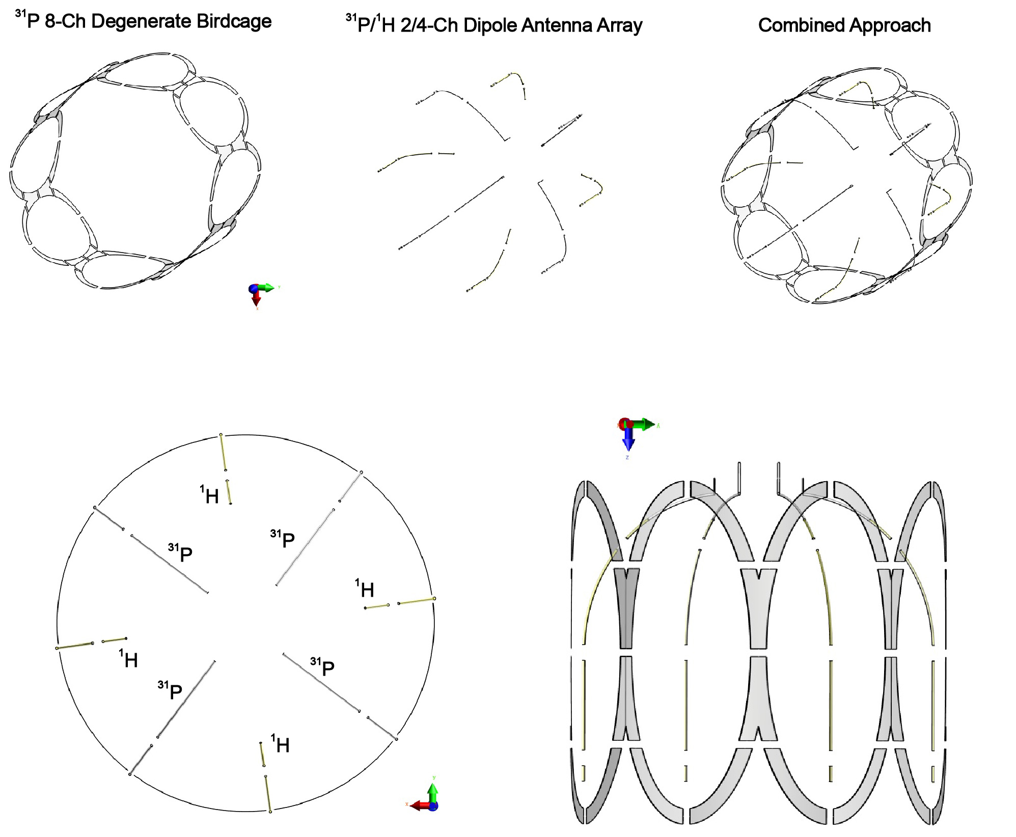
Fig.
1. Schematic view of the proposed 31P degenerate birdcage mixed with
bent dipole antennas (2-ch) and 4-ch 1H dipole array.
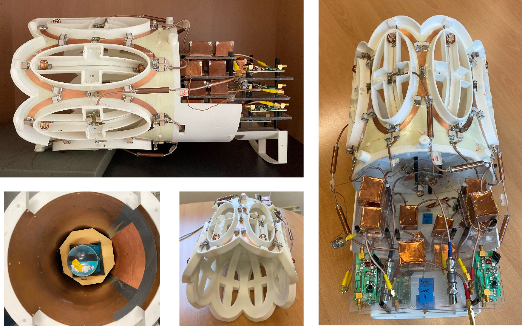
Fig.2. Constructed 31P degenerate birdcage with bent dipole
antennas, cable traps, and transmit/receive switches. The coil was loaded with
a spherical phantom and evaluated at the bench when placed inside a head
gradient insert (left corner in the Fig.).
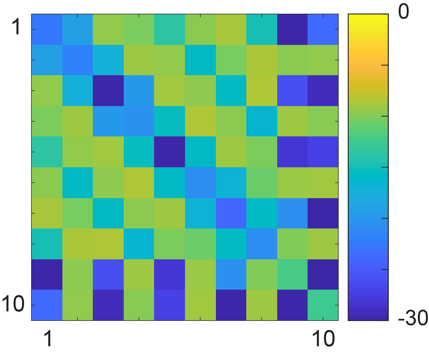
Fig.3.
S-matrix obtained from simulations when the 31P RF coil was loaded
with a spherical phantom (#1-8 – loop elements; #9,10 – dipole antennas).
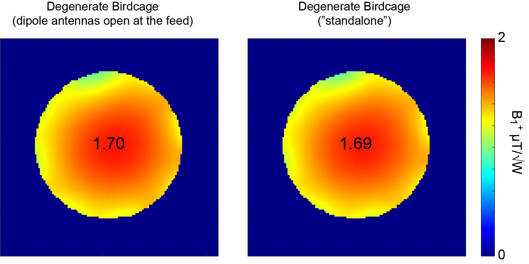
Fig.4.
Simulated B1+
distribution (CP mode) in a spherical phantom (axial view).
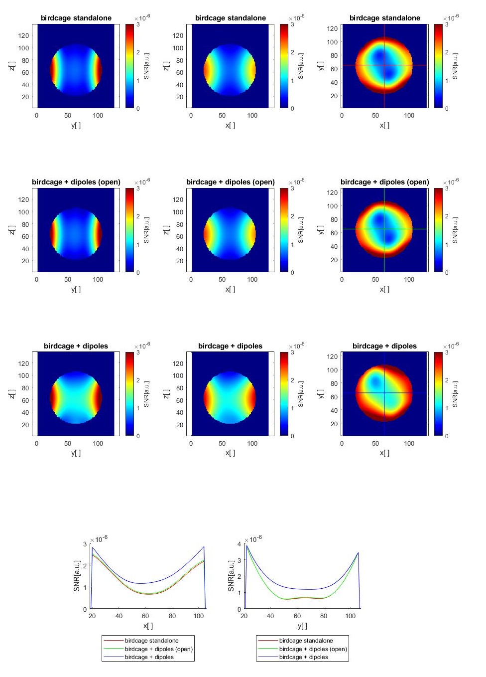
Fig. 5. Calculated
SNR maps calculated for: “standalone” 31P degenerate birdcage coil (top row), with open-
(middle) and tuned 31P dipole antennas (bottom).
The profiles across the phantom indicate that there was a 1.6- to 1.7-fold SNR increase for the combined array (blue line).
DOI: https://doi.org/10.58530/2023/0216