0214
Combined triple tuned X-nuclei (2H, 23Na, 31P) birdcage and 1H 4 channel dipole array for head imaging at 7T1Center for Advanced Imaging Innovation and Research (CAI2R), NYU School of Medicine, New York, NY, United States, 2Center for Biomedical Imaging, Department of Radiology, NYU School of Medicine, New York, NY, United States
Synopsis
Keywords: RF Arrays & Systems, RF Arrays & Systems
One method to achieve multiple coil resonances involves the use of diode or microelectromechanical system (MEMS) switches to toggle between resonances at proton and x-nuclei frequencies. While this approach provides a straightforward means to activate or deactivate coils corresponding to the desired nucleus, it does not allow simultaneous multinuclear data acquisition hat is required to eliminate temporal disparities. In this work we present a triple tuned birdcage for truly simultaneous imaging of X-nuclei combined with a proton dipole array at 7T. We show initial phantom imaging experiments and compare SNR with existing RF coils.Introduction
Abnormalities in brain energy metabolism are strongly linked to a variety of pathologies. Direct and concurrent quantitation of multiple energetic parameters and metabolites in the brain, such as glucose uptake and lactate generation, levels of ATP and phosphocreatine, or intracellular sodium concentration can provide fundamental insights into the changes in energy metabolism due to pathology or therapy. However, the temporal connection between metabolic activities in vivo is not available due to a lack of hardware and acquisition method. In this work, we developed a quadruple-tuned radiofrequency coil (1H, 23Na, 31P, 2H) as a first step toward quantifying multiple metabolic parameters simultaneously.One method to achieve multiple coil resonances involves the use of diode or microelectromechanical system (MEMS) switches to toggle between resonances at proton and x-nuclei frequencies1-3. While this approach provides a straightforward means to activate or deactivate coils corresponding to the desired nucleus, it does not allow simultaneous multinuclear data acquisition4,5 that is required to eliminate temporal disparities.
In this work we present a triple tuned birdcage for truly simultaneous imaging of X-nuclei combined with a proton dipole array at 7T. We show initial phantom imaging experiments and compare SNR with existing RF coils.
Methods
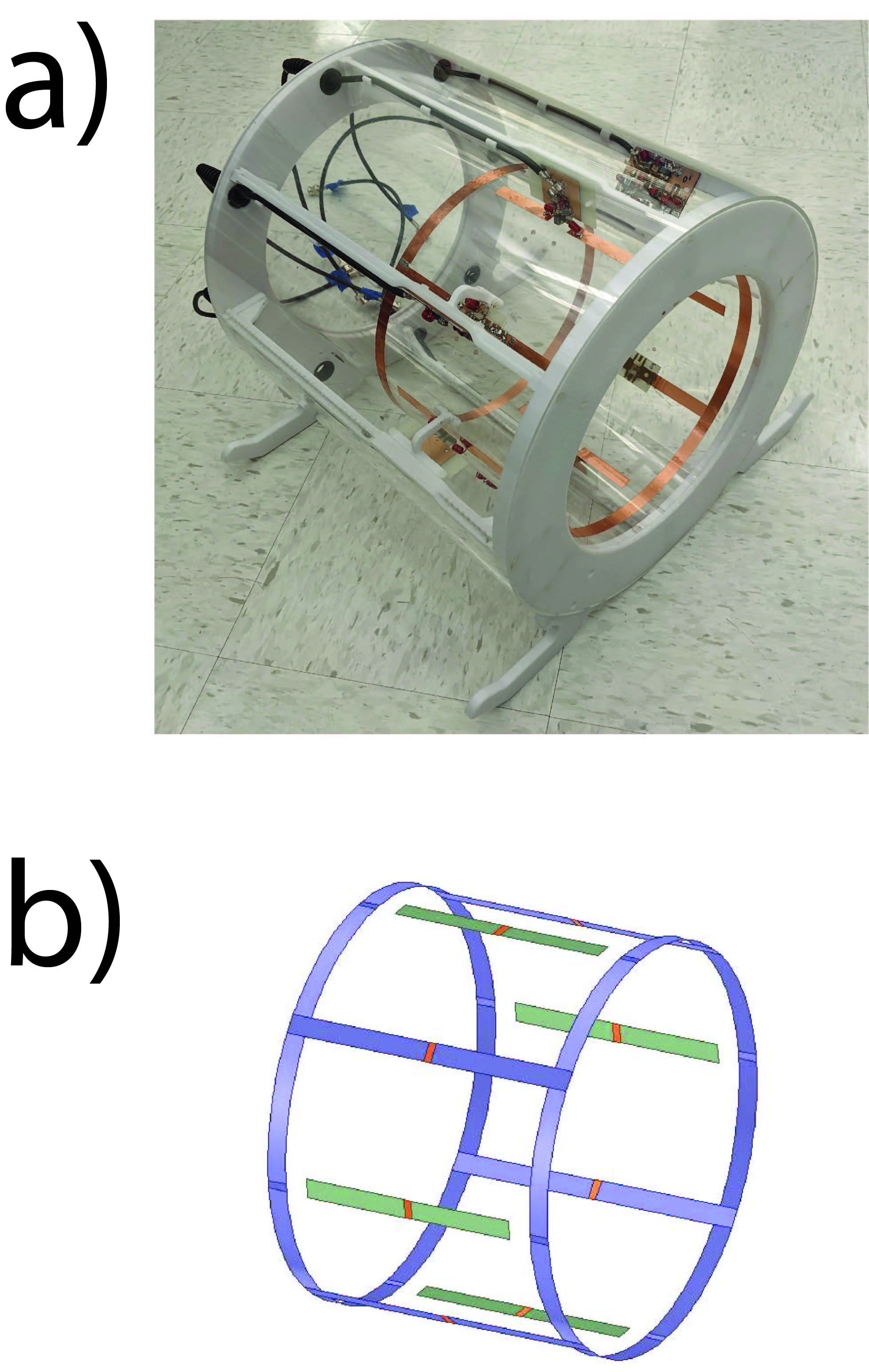
We decided to design a triple tuned X-nuclei coil (2H, 23Na, 31P f_Larmor=45,78,120MHz) and a separate array for 1H imaging (f_Larmor=297MHz). For a homogeneous field distribution we chose a lowpass birdcage design for the X-nuclei. A four rod configuration was chosen to show the proof-of-concept. To minimize the interaction with the X-nuclei coil we chose a four channel dipole array for proton imaging, see Fig1.Birdcage
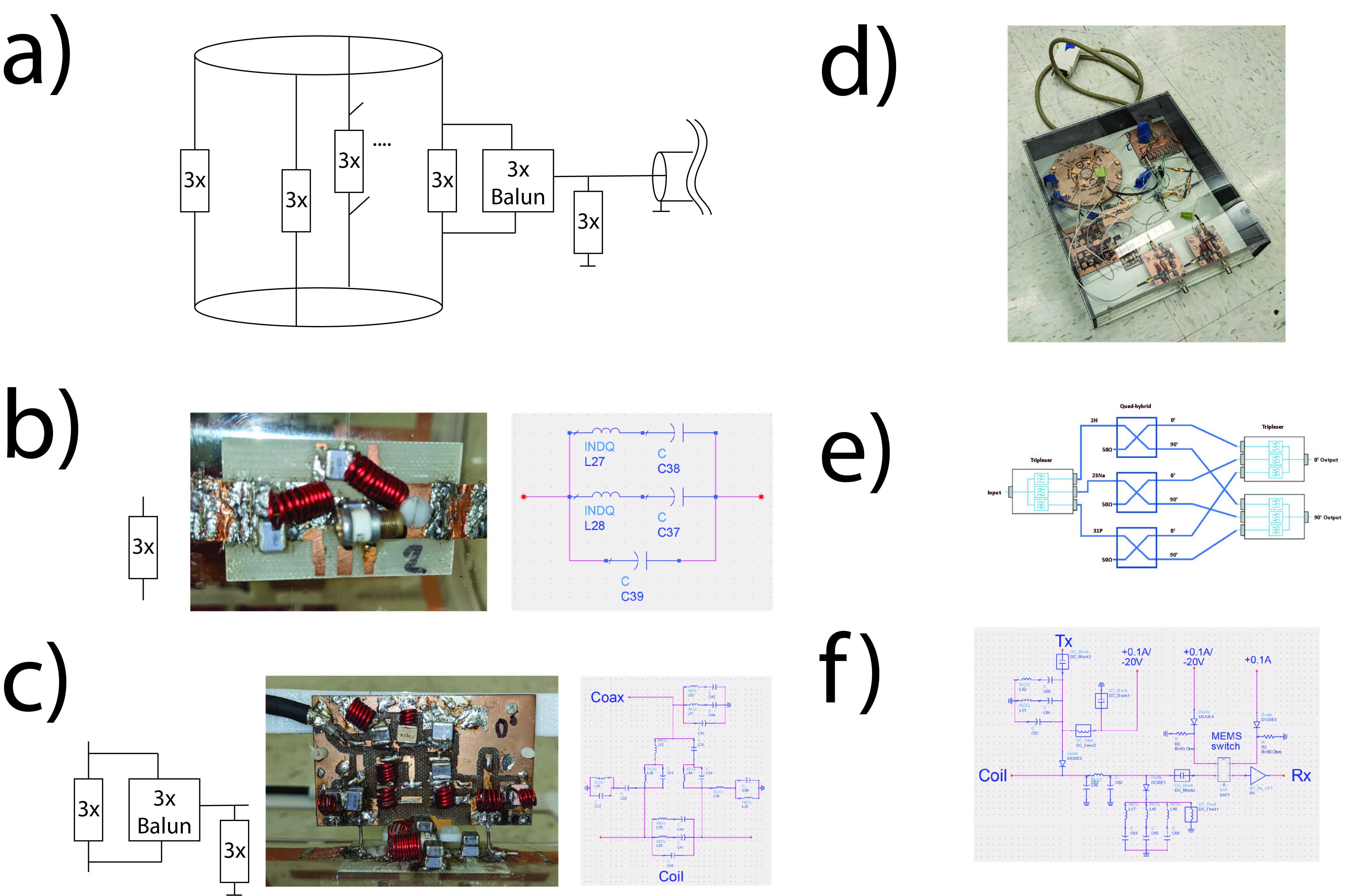
First, the capacitors for a single tuned birdcage were found for each Larmor frequency. The loading ratio of Q_0/Q_L=4.2,6.3,5.9, was measured for each larmor frequency respectively. To achieve triple-resonance we used a triple resonant network, 3x-network, see Fig2b., which was fine tuned to mimic the previously found capacitors for the single tuned case. The triple tuned birdcage has a loading ratio Q_0/Q_L=2.0,1.3,3.1 at the three frequencies. A triple tuned-balun was designed to limit cable currents. Before and after the balun, 3x-networks in parallel were used to match the birdcage modes6, Fig2c.
A dedicated TR interface was designed, Fig2d. In transmit-mode a quadrature signal for each frequency is generated Fig2e. During receive-mode the birdcage modes are treated as independent channels. Two triple tuned TR switches were designed based on a single tuned design7, Fig2f. A broadband low-noise preamplifier (WBA0001B, WanTcom, Chanhassen, MN, USA) was used for preamplification. The isolation of the TR switch had to be increased with a MEMS switch (BGS12PN10, Infineon, Munich, Germany) due to the low maximal input power of the preamp (15dBm).
1H dipole array
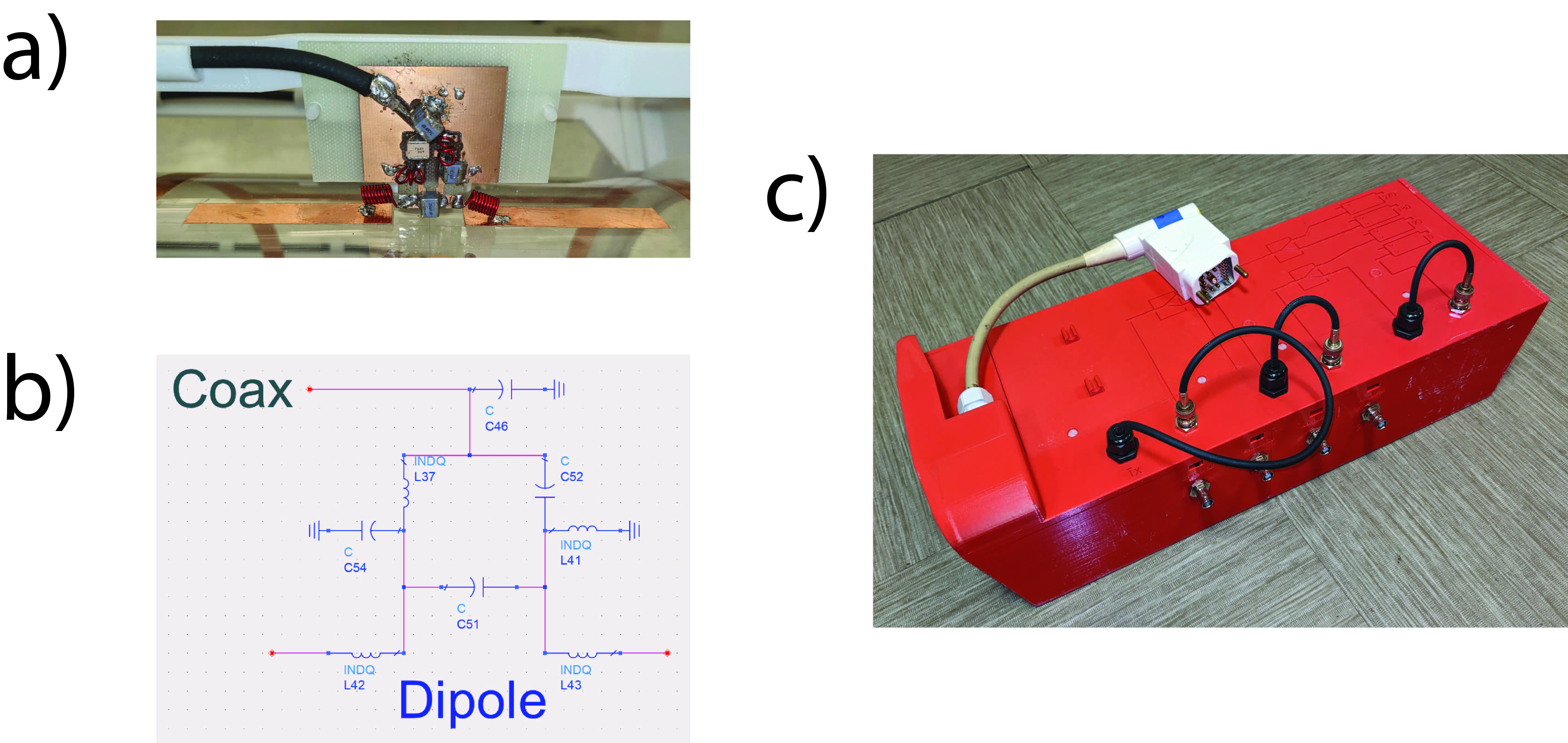
Each dipole had a length of 145mm and was driven through a lattice balun to minimize cable currents. The dipoles were electrically lengthened with inductors in the feed-port. Matching to 50Ohms was achieved with parallel trimmer capacitors before and after the balun, Fig3a,b. The dipole array was driven in quadrature while each dipole has its own receive channel, using a TR box Fig3c.
Imaging experiments
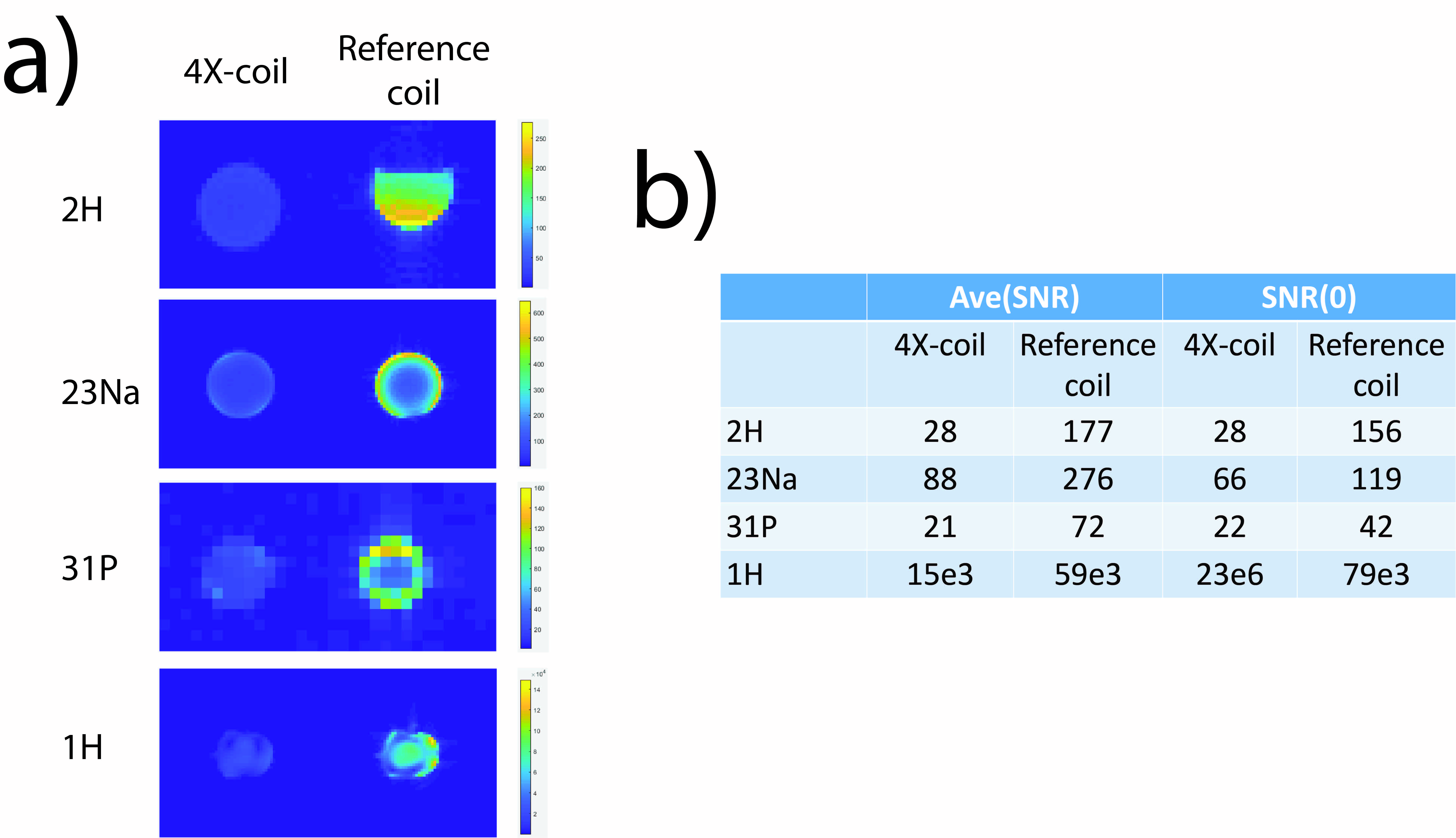
Imaging experiments were conducted on a MAGNETOM 7T MRI system (Siemens Healthineers, Erlangen Germany). We compared SNR in the transversal slice. Sodium and phosphorus were compared to previously published arrays8,9, at 1H we compared to the 32 channel head coil (Nova Medical Inc., MA, USA). For a lack of a coil at deuterium we used a rectangular loop coil (L=19cm, W=9cm, conductor width=1cm) as a reference. The phantoms used were a 500ml bottle with pure Deuterium for 2H, head-sized cylindrical phantoms for sodium and phosphorus, and a head phantom at proton. The local oscillator of the scanner had to be modified to enable 2H imaging because it is not supported on our system10.
Results and Discussion
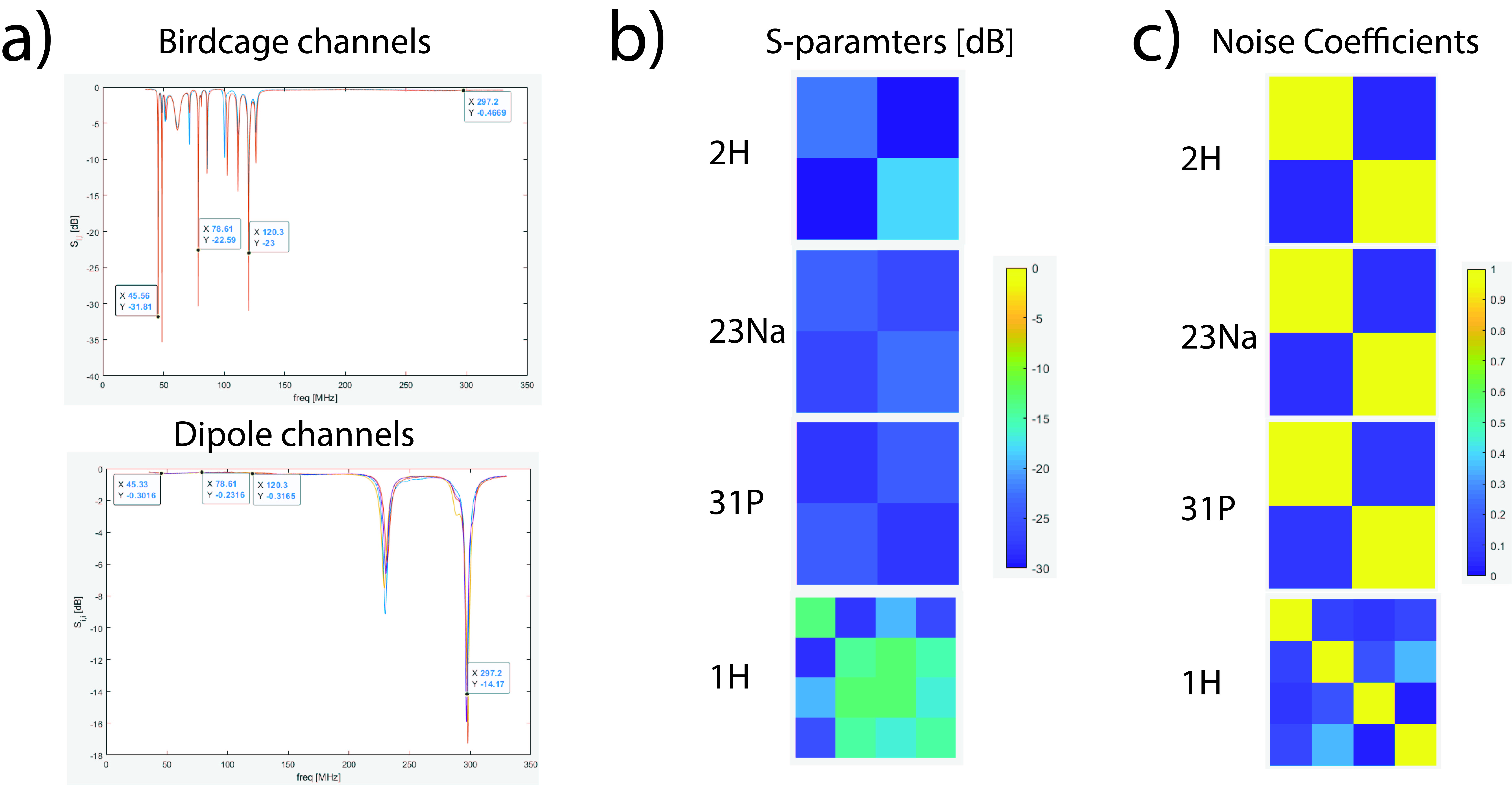
Scattering-parameters of the coil array are shown in Fig4a,b. Coupling between the two birdcage modes was -30,-26, and -24dB at the three X-nuclei larmor frequencies. The maximal coupling of the dipole array was -13dB. The birdcage channels had no resonance close to the dipole channels' resonant modes and vice-versa showing negligible interaction between the two sub-coils. The SNR comparison to existing arrays is shown in Fig5a. The SNR is evaluated in a table in Fig5b. The lower SNR of the triple tuned birdcage has two reasons, firstly due to the homogeneous field distribution of the quadrature birdcage coil, resulting in a lower sensitivity in the periphery. And secondly, due to the additional loss of the 3x network, the triple tuned Balun and the TR-interface, resulting in a global degradation of SNR.Conclusion and Outlook
We present a quadruple tuned RF coil and compare it to existing coil arrays. Several novelties were introduced such as a triple tuned quadrature birdcage and a triple tuned lattice balun. While the SNR of the quadruple tuned coil was significantly lower than dual- and single-tuned reference coils, it represents a step toward truly simultaneous measurements. Although challenging due to the steep impedance curves of the 3x network, other circuit topologies will be explored to reduce loss.Acknowledgements
No acknowledgement found.References
1. Ha S, Hamamura MJ, Nalcioglu O, Muftuler LT. A PIN diode controlled dual-tuned MRI RF coil and phased array for multi nuclear imaging. Phys Med Biol. 2010;55(9):2589-2600.
2. Maunder A, Rao M, Robb F, Wild JM. Comparison of MEMS switches and PIN diodes for switched dual tuned RF coils. Magn Reson Med. 2018;80(4): 1746-1753.
3. Choi CH, Hong SM, Ha Y, Shah NJ. Design and construction of a novel (1)H/(19)F double-tuned coil system using PIN-diode switches at 9.4T. J Magn Reson. 2017;279:11-15.
4. Liu Y, De Feyter HM, Fulbright RK, McIntyre S, Nixon TW, de Graaf RA. Interleaved fluid-attenuated inversion recovery (FLAIR) MRI and deuterium metabolic imaging (DMI) on human brain in vivo. Magn Reson Med. 2022 Jul;88(1):28-37. doi: 10.1002/mrm.29196. Epub 2022 Feb 28. PMID: 35225375.
5. Yu Z, Madelin G, Sodickson DK, Cloos MA. Simultaneous proton magnetic resonance fingerprinting and sodium MRI. Magn Reson Med. 2020 Jun;83(6):2232-2242. doi: 10.1002/mrm.28073. Epub 2019 Nov 20. PMID: 31746048; PMCID: PMC7047525.
6. Zhu Y, Sappo CR, Grissom WA, Gore JC, Yan X. Dual-Tuned Lattice Balun for Multi-Nuclear MRI and MRS. IEEE Trans Med Imaging. 2022 Jun;41(6):1420-1430. doi: 10.1109/TMI.2022.3140717. Epub 2022 Jun 1. PMID: 34990352.
7. Shajan G, Hoffmann J, Budde J, Adriany G, Ugurbil K, Pohmann R. Design and evaluation of an RF front-end for 9.4 T human MRI. Magn Reson Med. 2011 Aug;66(2):596-604. doi: 10.1002/mrm.22808. Epub 2011 Mar 4. PMID: 21381102.
8. Bili Wang, Bei Zhang, Zidan Yu, Carlotta Ianniello, Karthik Lakshmanan, Jan Paska, Guillaume Madelin, Martijn Cloos, Ryan Brown, A Radially Interleaved Sodium and Proton Coil Array for Brain MRI at 7 Tesla. NMR in Biomedicine, Vol 34, Issue 12, pp.e4608, 2021.
9. Brown, R., Lakshmanan, K., Madelin, G. & Parasoglou, P. A nested phosphorus and proton coil array for brain magnetic resonance imaging and spectroscopy. Neuroimage 124, 602-611, doi:10.1016/j.neuroimage.2015.08.066 (2016).
10. Umathum R, Rösler MB, Nagel AM. In vivo 39K MR imaging of human muscle and brain. Radiology. 2013 Nov;269(2):569-76. doi: 10.1148/radiol.13130757. Epub 2013 Jul 22. PMID: 23878285.
Figures