0213
Using the end of the feeding cable directly as a flexible antenna at 7T: the coax monopole antenna1Electrical Engineering, Eindhoven University of Technology, Eindhoven, Netherlands, 2Biomedical Engineering, Eindhoven University of Technology, Eindhoven, Netherlands, 3Division of Imaging and Oncology, UMC Utrecht, Utrecht, Netherlands
Synopsis
Keywords: RF Arrays & Systems, High-Field MRI
This work introduces the coax monopole antenna. The antenna consists of a continuation of the feeding cable and uses only one inductor at the distal side of the antenna to achieve matching. Creating a radiative antenna is done by introducing one interruption in the shield of the coaxial cable, and the antenna length is enforced using a cable trap. Simulations and measurements show that the performance of this antenna is comparable to the fractionated dipole antenna, while introducing many advantages like easy cable routing, proper loading of the coil due to its flexibility, and easy construction.Introduction
The use of coaxial cables to build RF coils has seen extensive applications in the MRI community because of their flexibility and homogeneous current profiles1–5. Typically these coils are driven at the core of the coaxial cable while one or more slits in the shield cause the currents on the inside of the cable to extend to the outside of the shield and radiate/detect RF fields. Although most coaxial cable coils focus on loop coil designs, recently Van Leeuwen et al. published their ‘coax dipole’ for use as a transmit/receive array element for ultrahigh field body imaging4. It consists of a coaxial cable dipole antenna with two slits in the shield and end-of-line inductors to avoid reflections. A downside of this and every other dipole antenna is that it is fed in the center. Therefore, the feeding cable needs to run parallel to one of the legs of the dipole antenna which increases the potential for antenna-cable coupling. A more elegant solution is to use monopole antennas6,7. In this work we present the coax monopole antenna, which is based on the same operating principles as the coax dipole. One of the unique features of this antenna is that the antenna and the feeding cable are one and the same. The only matching component (an inductor) is placed at the distal end of the coaxial cable.Methods
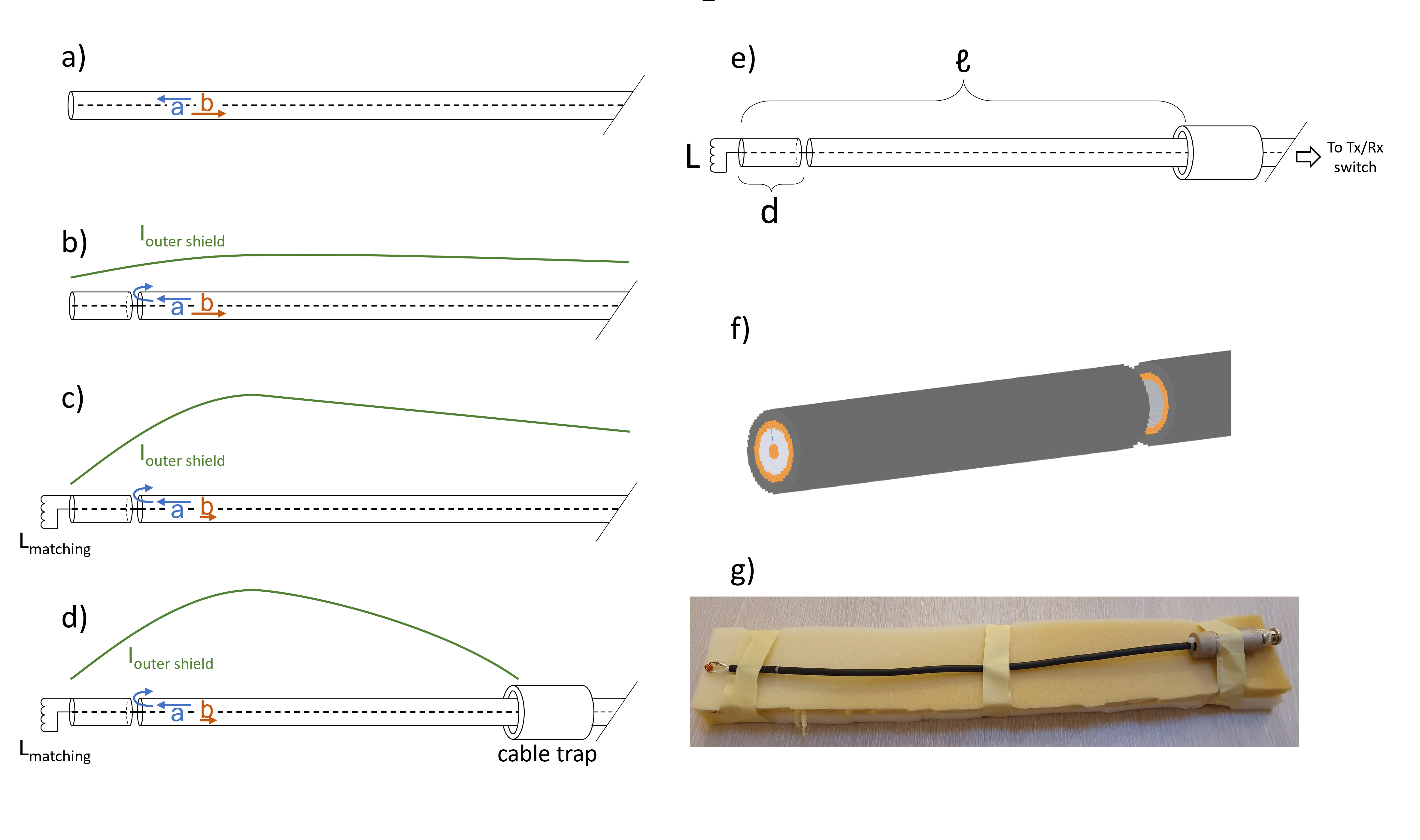
A schematic depiction of the coax monopole antenna (CMA) is presented in Figure 1. The shield of the coaxial cable is interrupted by a gap at distance d from the end, which allows for current to flow to the outside of the shield, creating a radiative cable (1b). Matching is achieved at the distal side of the antenna, where an inductor L is used to connect the shield to the core of the coaxial cable, which will reduce reflection (1c)4.The length ℓ of the antenna is enforced by a cable trap at the desired position (1d).FDTD simulations (Sim4Life, Zurich MedTech, Switzerland) are used to find the optimal length ℓ, gap position d and inductance L, and to evaluate the B1+ and local SAR distributions. After determining the optimal parameters for the antenna, one CMA was constructed. A single channel B1+ map was acquired on a homogeneous phantom (polyvinylpyrrolidone8, σ = 0.5 S/m, εr = 46) at 7T (Achieva, Philips Healthcare, Best, The Netherlands). These measurements were also carried out with fractionated dipoles for comparison11 and both setups were also simulated for B1+ and SAR level comparison. Subsequently, an array of eight CMAs was constructed and characterized by its S-parameter matrix, prostate imaging and B1+ measurements.
Results
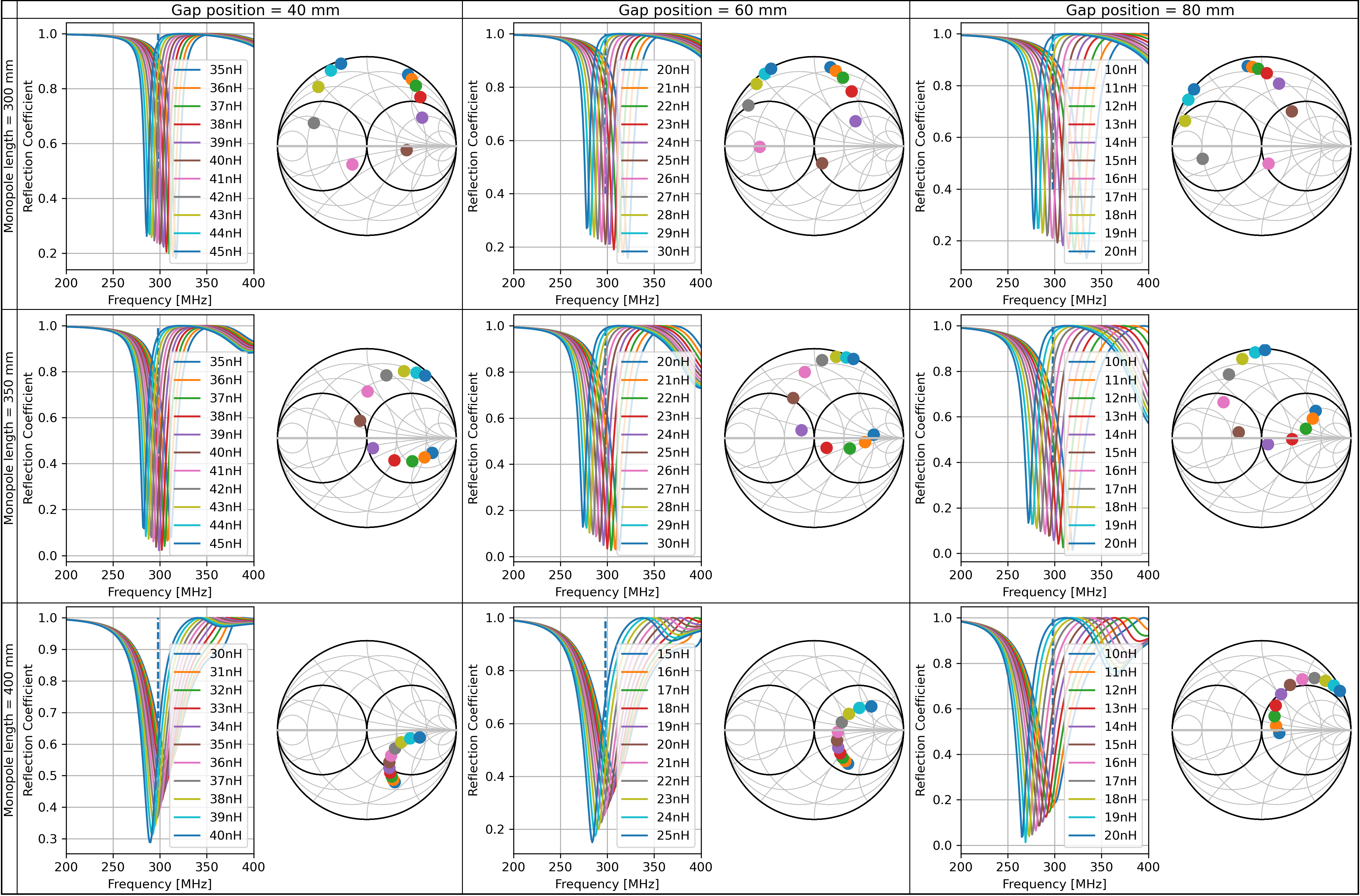
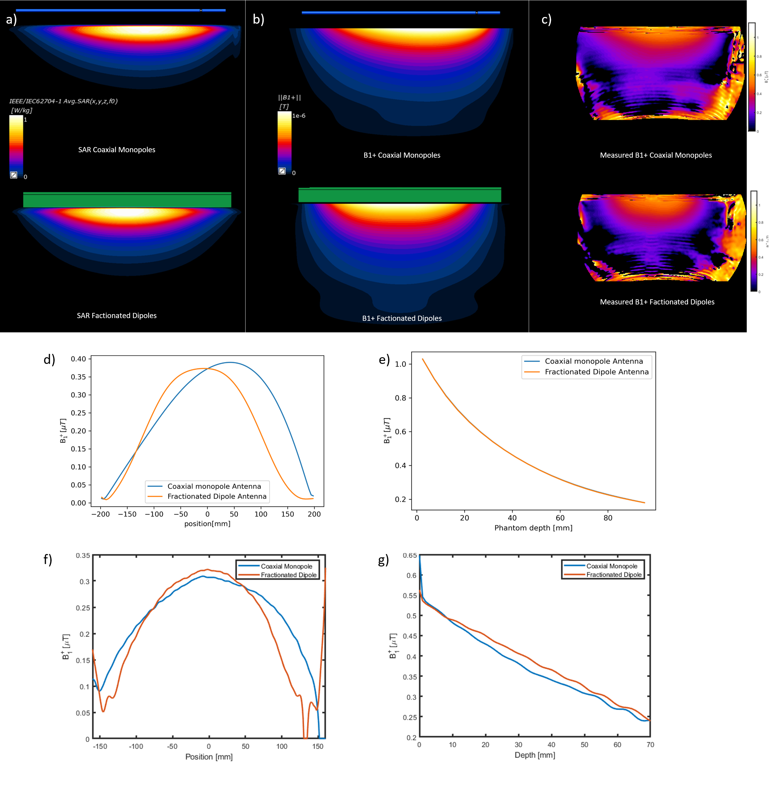
Figure 2 shows the smith charts and corresponding reflection plots for the investigated values of ℓ, d and L. Note that simulated B1+ and SAR distributions for the investigated parameters did not show considerable differences (data not shown). Based on these results, ℓ =35cm and d=40mm proved most beneficial for matching and a uniform B1+ distribution. This antenna was built with L being a self-wound inductor (Figure 1g).Figures 3a and 3b show the 10g averaged SAR and B1+ distributions of single-channel simulations on a homogeneous phantom for CMA and fractionated dipole. Both antennas reach the same peak local SAR level of 1.0 W/kg. The B1+ profile of the CMA is slightly skewed in the direction of the gap, but is also wider than the fractionated dipole. 7T measurements confirm that the B1+ amplitude is comparable to the fractionated dipole, as shown in Figures 3c-g.
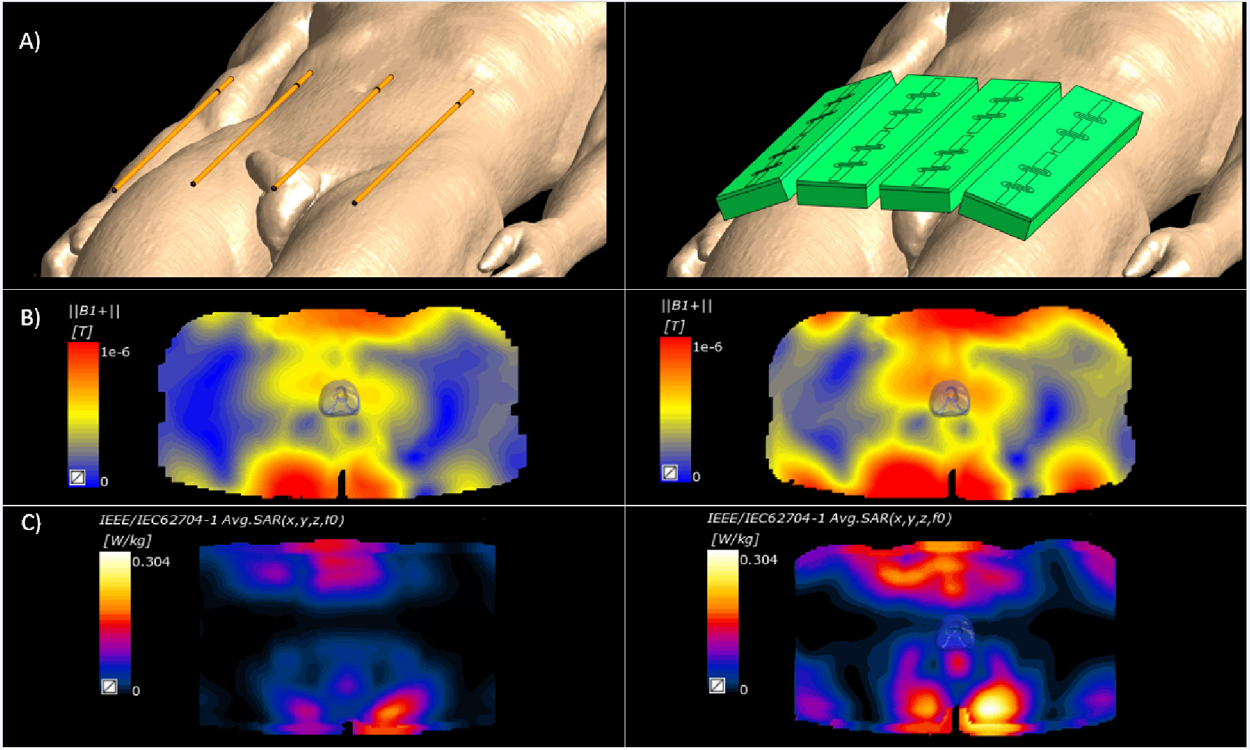
The simulation setup for the array simulations on Duke and resulting B1+ and SAR distributions, both for the CMA and fractionated dipole, are shown in Figure 4. Lower SAR levels are found for the CMA, at the cost of slightly lower B1+. The B1+ /√(SARmax) ratio is 0.39 uT/√(W/kg) for the CMA, and 0.375 μT/√(W/kg) for the fractionated dipole.
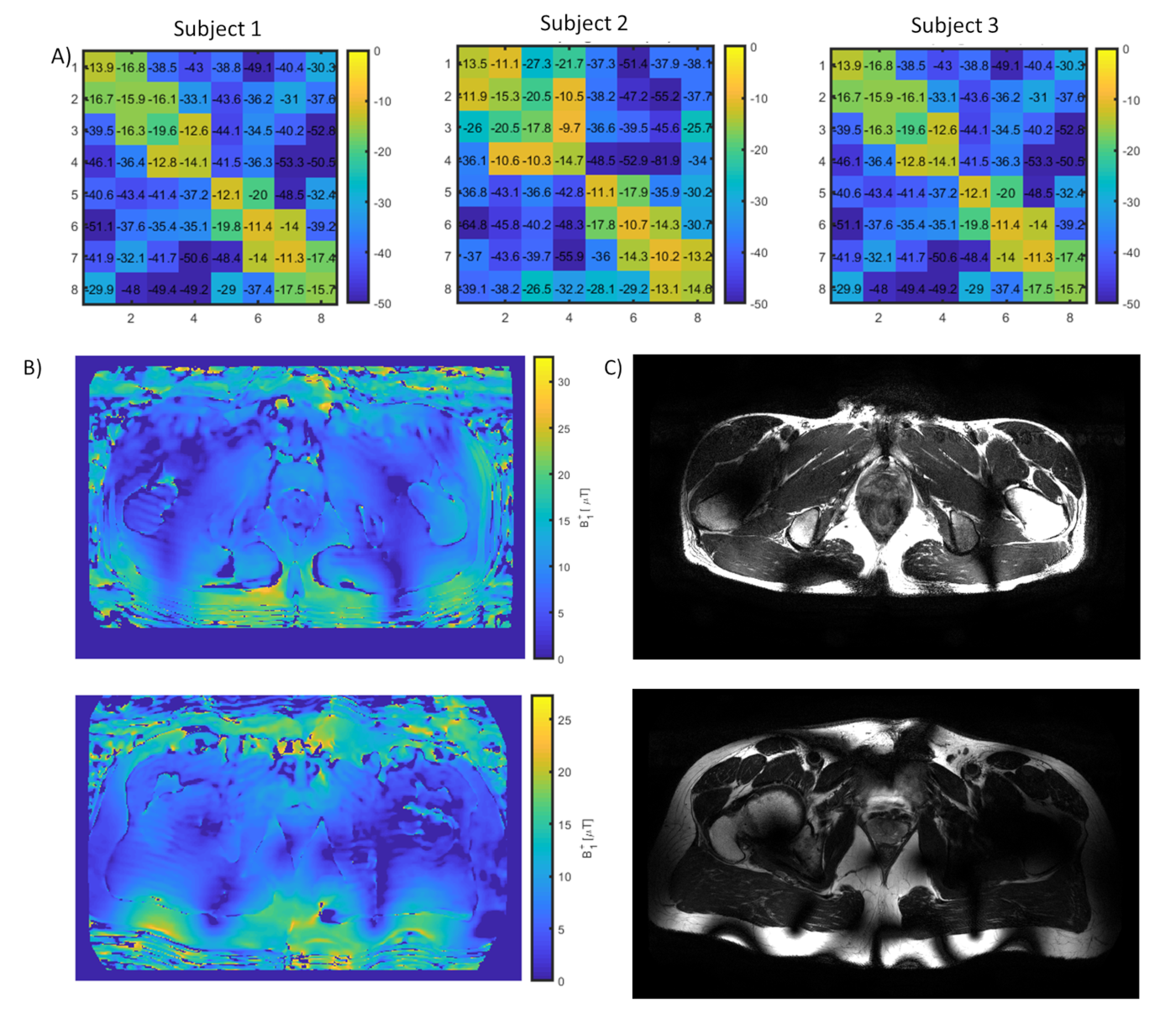
Reflection and inter-element coupling was acceptable for three volunteers, as shown in Figure 5a. B1+ levels within the prostate were 10 and 12 μT for the two volunteers while good quality T2-weighted prostate images were acquired (Figures 5b and 5c).
Discussion
Overall, results indicate that the CMA and Fractionated Dipole perform more or less comparable. Coax monopoles have a slightly better SAR efficiency than the fractionated dipoles (4%) at the cost of a lower average B1+, which is distributed over a larger field of view. This is similar to results obtained with previous antennas optimized for SAR efficiency 4,10-12. The benefit of the coax monopole lies mainly in its flexibility, convenient cable routing and easier construction. Also worth noting is the unique characteristic of the antenna being a seamless continuation of the feeding cable while the matching component is placed at the distal end of the cable.Conclusion
The coax monopole antenna is presented as a novel antenna for 7T imaging. It is an extension of the feeding cable with a single matching inductor at the ending of the antenna. Because the antenna is one with the feeding cable, cable routing is easy, and the flexibility of the cable improves equal distribution of the load over the antenna.Acknowledgements
No acknowledgement found.References
[1] B. Zhang, D. K. Sodickson, and M. A. Cloos, “A high-impedance detector-array glove for magnetic resonance imaging of the hand,” Nat. Biomed. Eng., vol. 2, no. 8, pp. 570–577, 2018.
[2] T. Ruytenberg, A. Webb, and I. Zivkovic, “Shielded-coaxial-cable coils as receive and transceive array elements for 7T human MRI,” Magn. Reson. Med., 2020.
[3] L. Nohava, R. Czerny, S. Roat, M. Obermann, A. Kuehne, R. Frass-Kriegl, J. Felblinger, J. C. Ginefri, and E. Laistler, “Flexible Multi-Turn Multi-Gap Coaxial RF Coils: Design Concept and Implementation for Magnetic Resonance Imaging at 3 and 7 Tesla,” IEEE Trans. Med. Imaging, 2021.
[4] C. C. van Leeuwen, B. R. Steensma, D. W. J. Klomp, C. A. T. van den Berg, and A. J. E. Raaijmakers, “The Coax Dipole: A fully flexible coaxial cable dipole antenna with flattened current distribution for body imaging at 7 Tesla,” Magn. Reson. Med., 2021.
[5] S. E. Zijlema, R. H. N. Tijssen, V. N. Malkov, L. Van Dijk, S. L. Hackett, J. G. M. Kok, J. J. W. Lagendijk, and C. A. T. Van Den Berg, “Design and feasibility of a flexible, on-body, high impedance coil receive array for a 1.5 T MR-linac,” Phys. Med. Biol., 2019.
[6] M. K. Woo, L. Delabarre, M. Waks, J. Lee, R. L. Lagore, S. Jungst, A. Grant, Y. Eryaman, K. Ugurbil, and G. Adriany, “Comparison of 16-Channel Asymmetric Sleeve Antenna and Dipole Antenna Transceiver Arrays at 10.5 Tesla MRI,” IEEE Trans. Med. Imaging, vol. 40, no. 4, pp. 1147–1156, 2021.
[7] S. M. Hong, J. H. Park, M. K. Woo, Y. B. Kim, and Z. H. Cho, “New design concept of monopole antenna array for UHF 7T MRI,” Magn. Reson. Med., vol. 71, no. 5, pp. 1944–1952, 2014.
[8] C. Ianniello, J. A. de Zwart, Q. Duan, C. M. Deniz, L. Alon, J. S. Lee, R. Lattanzi, and R. Brown, “Synthesized tissue-equivalent dielectric phantoms using salt and polyvinylpyrrolidone solutions,” Magn. Reson. Med., vol. 80, no. 1, pp. 413–419, 2018.
[9] A. J. E. Raaijmakers, M. Italiaander, I. J. Voogt, P. R. Luijten, J. M. Hoogduin, D. W. J. Klomp, and C. A. T. Van Den Berg, “The fractionated dipole antenna: A new antenna for body imaging at 7 Tesla,” Magn. Reson. Med., vol. 75, no. 3, pp. 1366–1374, 2016.
[10] I. Zivkovic, C. A. Castro, and A. Webb, “Design and characterization of an eight‐element passively fed meander‐dipole array with improved specific absorption rate efficiency for 7 T body imaging,” NMR Biomed., no. March, p. e4106, 2019.
[11] A. Sadeghi-Tarakameh, G. Adriany, G. J. Metzger, R. L. Lagore, S. Jungst, L. DelaBarre, P. F. Van de Moortele, K. Ugurbil, E. Atalar, and Y. Eryaman, “Improving radiofrequency power and specific absorption rate management with bumped transmit elements in ultra-high field MRI,” Magn. Reson. Med., vol. 84, no. 6, 2020.
[12] B. Steensma, P. F. van de Moortele, A. Ertürk, A. Grant, G. Adriany, P. Luijten, D. Klomp, N. van den Berg, G. Metzger, and A. Raaijmakers, “Introduction of the snake antenna array: Geometry optimization of a sinusoidal dipole antenna for 10.5T body imaging with lower peak SAR,” Magn. Reson. Med., 2020.
[13] Yarnykh VL. Actual flip-angle imaging in the pulsed steady state: A method for rapid three-dimensional mapping of the transmitted radiofrequency field. Magn Reson Med. 2007;57(1):192-200.
Figures