0212
Dynamic dipole receive coils for improved 3D parallel imaging at ultra-high magnetic field1High-field Magnetic Resonance Center, Max Planck Institute for Biological Cybernetics, Tübingen, Germany, 2Department of Biomedical Magnetic Resonance, Eberhard Karls University Tübingen, Tübingen, Germany
Synopsis
Keywords: RF Arrays & Systems, High-Field MRI
Parallel imaging with electronically modulated time-varying receive sensitivities is a novel concept for improved reconstruction quality and reduced noise amplification. Previously, it was demonstrated for 2D imaging using reconfigurable surface loop receive elements. In the present work, we extend the approach to 3D imaging and for that introduce a reconfigurable single-row dipole receive array. By using PIN diodes to switch between capacitive and inductive impedance in the dipole arms, spatially distinct sensitivity profiles are formed that can be rapidly modulated. This is shown to enable parallel imaging acceleration along the dipole’s axis and improve reconstruction quality compared to static sensitivities.Introduction
We have recently presented a novel approach of dynamically modulating the receive sensitivity profiles of surface loop elements during MR signal acquisition for improved parallel imaging (PI) performance1. The initial study focused on 2D imaging with in-plane sensitivity variation, where achievable g-factor improvements were limited by partially overlapping profiles. The objective of the present work is to extend the approach to 3D imaging with sensitivity variation along the z-axis (head-foot direction). For that, we propose a novel RF Rx array coil design based on reconfigurable folded-end dipole elements, which allows dynamic sensitivity variation along the dipole’s axis. This is demonstrated to enable the application of PI along the z-axis with just a single row of receive elements.Methods
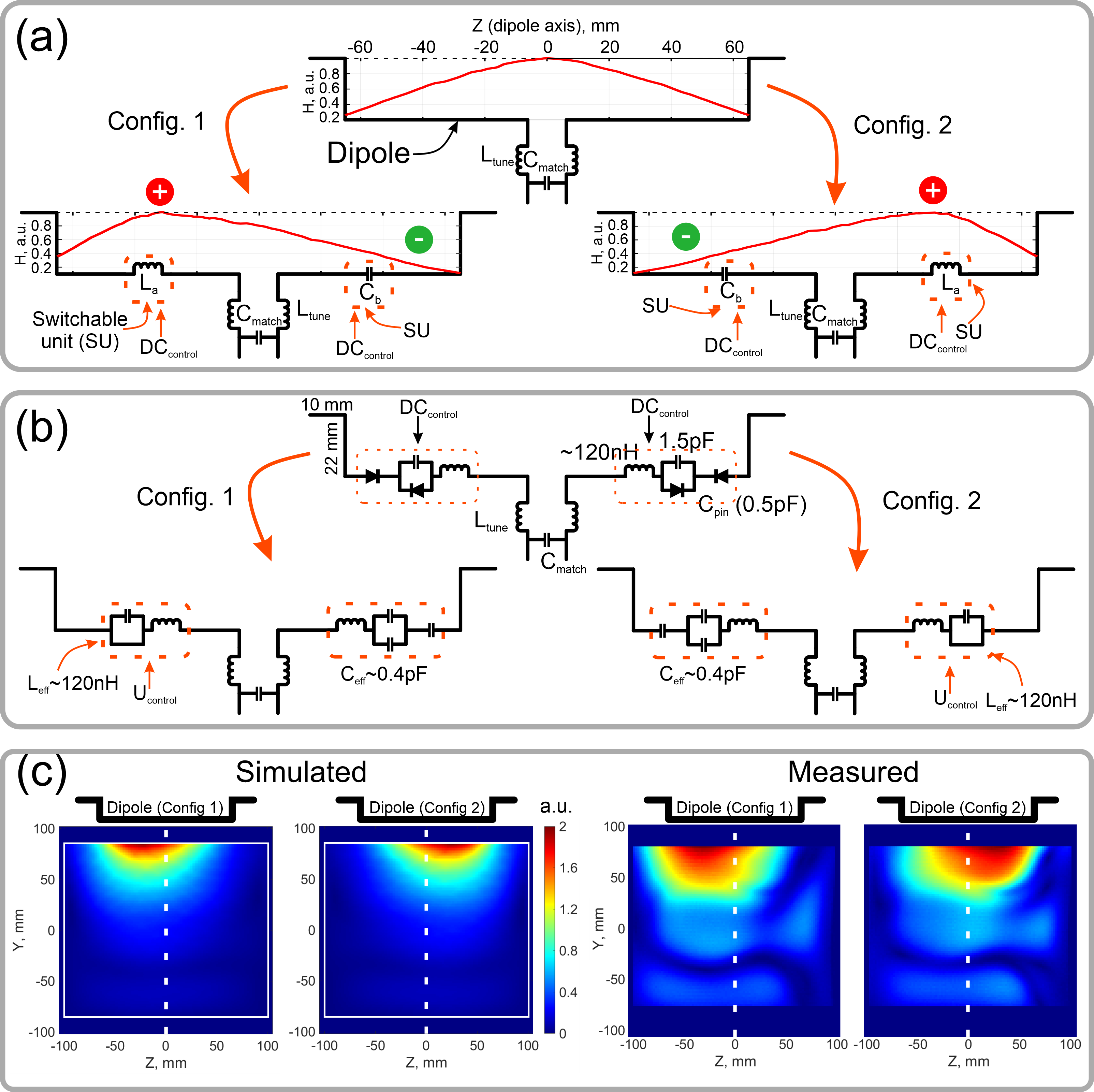
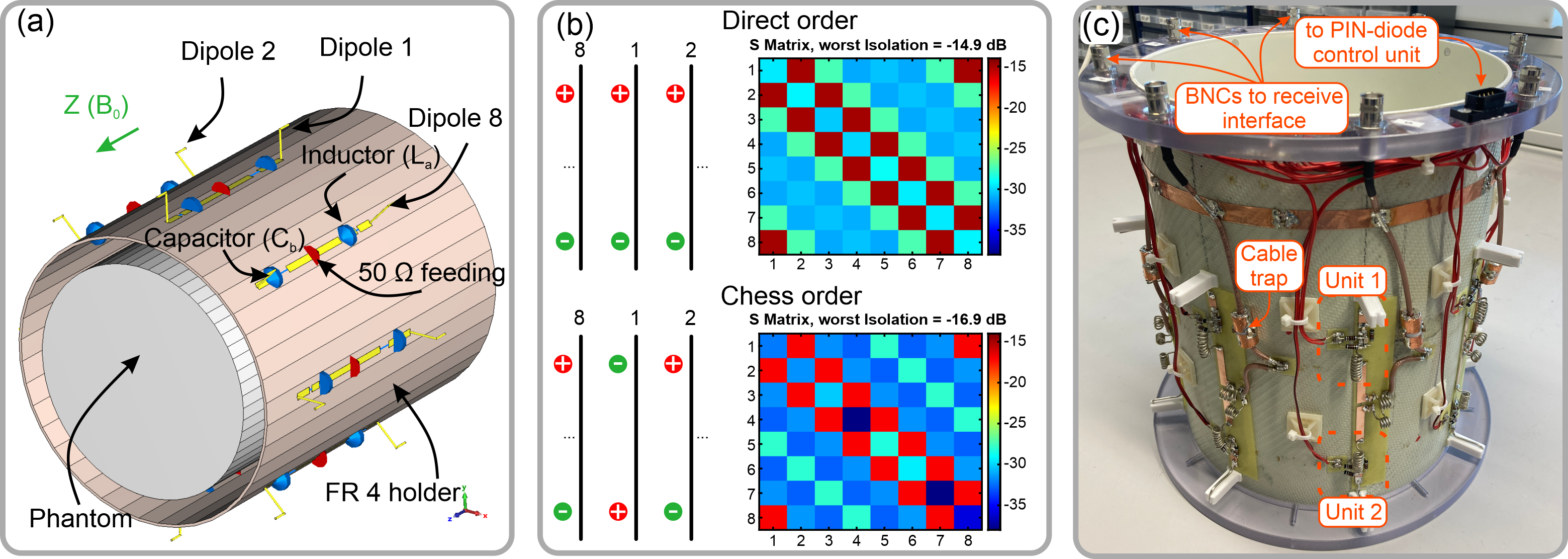
dipole array coil designThe array consists of 8 folded-end dipole elements2 equally distributed around a cylindrical surface (diameter 210 mm, Figure 2a). The principle of the reconfigurable dipole element is based on manipulation of the current distribution along the dipole length (Figure 1a). For that, an electronically controlled switchable unit (SU) was inserted in each dipole arm (Figure 1a,b). The SU is based on PIN-diodes (Figure 1b) and can change its impedance between capacitive and inductive. If the PIN diodes of one SU are positively biased, the impedance of the SU becomes inductive, which effectively increases the dipole’s electrical length. In negative bias, the impedance of the capacitors compensates the inductive impedance and the whole impedance of the SU becomes capacitive, which corresponds to a decrease in the electrical length. Switching of the PIN diodes was controlled via a custom-built CMOS driver connected to the optical trigger output of the scanner system. Electromagnetic simulations of the dipole array were performed using CST Studio Suite 2021 (Dassault Systèmes, Vélizy-Villacoublay, France).
MR imaging
Data were acquired on a 9.4T human whole-body MR scanner (Siemens Healthineers, Erlangen, Germany) using a 3D RF and gradient spoiled GRE sequence (TR/TE=20ms/8ms, FA=20°, matrix size 200x200x60, FOV=220mm x 220mm x 120mm, 20% slice oversampling, acquisition time 4min48s). Data were acquired in a cylindrical phantom and in a healthy subject after written informed consent and under approval of the local ethics committee. 20-fold readout oversampling was applied for an ADC dwell time of 1µs, while switching between the configurations every 10µs. This allows imaging of the repetitive switching dynamics with 1µs time resolution and thus multiplexing information from both spatial sensitivity configurations1. To correct for image artifacts that arise from the switching electronics, robust PCA3,4 was applied as described previously1. Further processing steps comprised pre-whitening, coil sensitivity extraction (ESPIRIT5, using the central 48x48 k-space lines) retrospective k-space undersampling and SENSE6 reconstruction for the cases of switched and static sensitivity configurations. G-factors were calculated according to equations 2 and 3 in 1.
Results
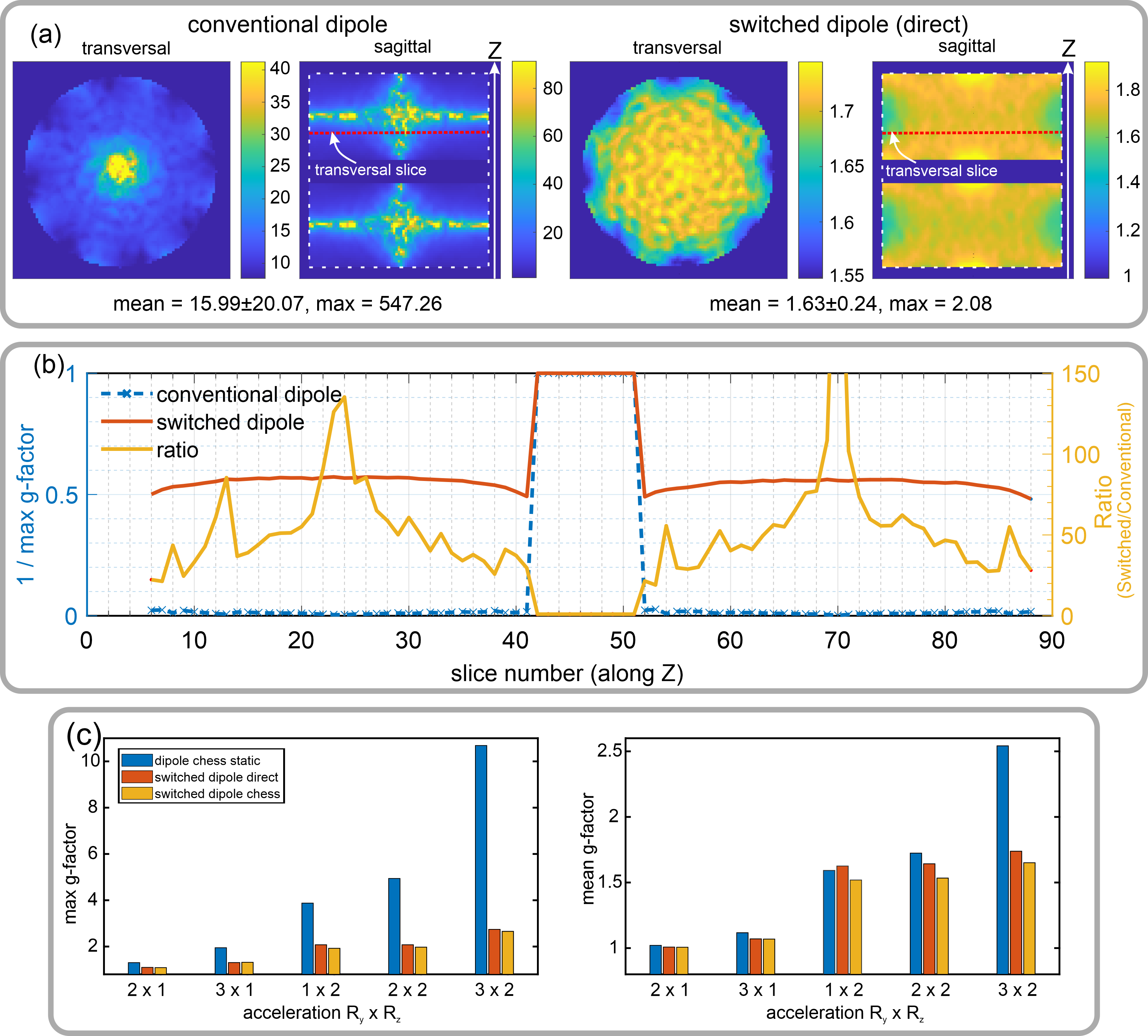
As demonstrated in Figure 1c for both simulation and measurement, the two configurations result in distinct asymmetric sensitivity profiles along the dipole axis. In contrast to a single row of conventional dipoles with symmetric sensitivity profile (Figure 1a, top), switching rapidly between the two asymmetric profiles effectively emulates two rows of receive elements. This allows using PI acceleration factor 2 along the z-axis while maintaining feasible g-factors, which is not possible with conventional dipoles (Figure 3).As a result of the simulations, it turned out that driving the dipoles in so-called “chess” order (Figure 2b) provided better isolation among the elements compared to the “direct” order (Figure 2b) and also resulted in slightly lower g-factors (Figure 3c).
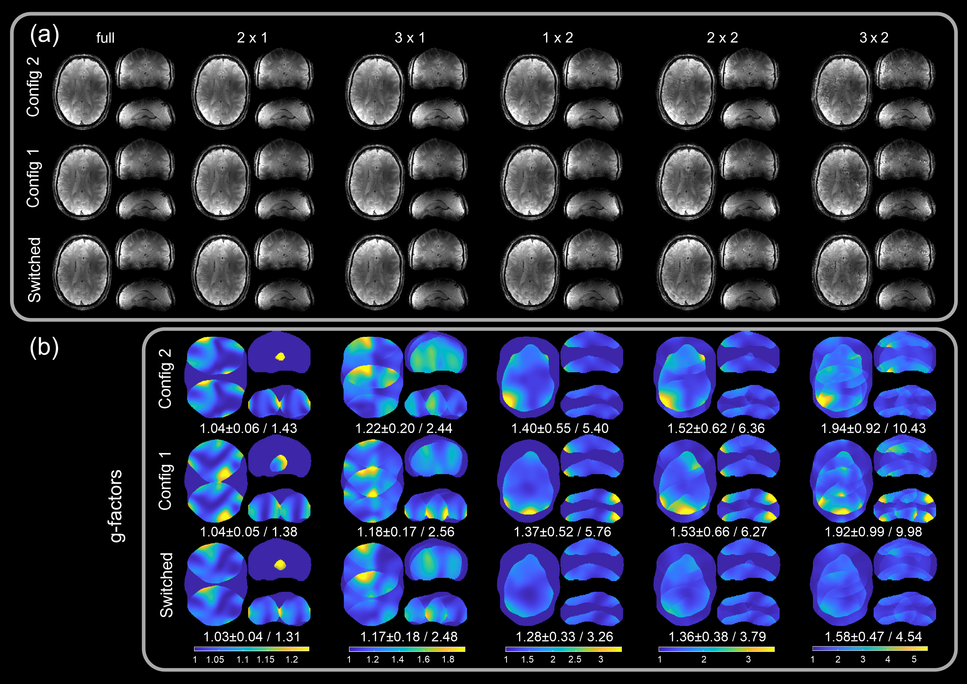
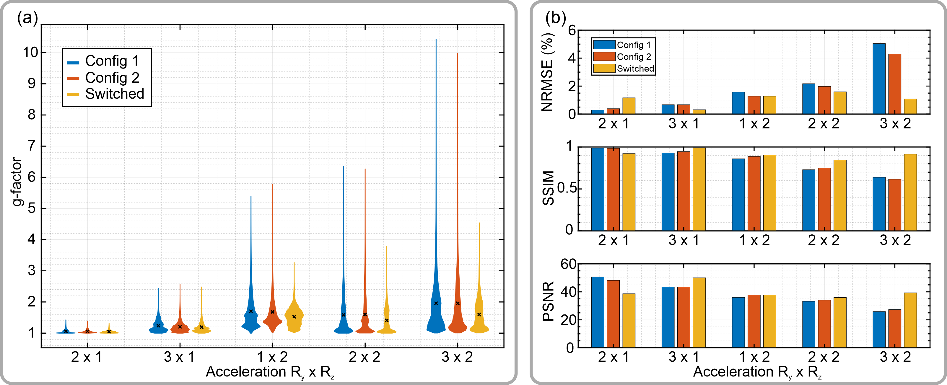
In Figure 4, in vivo parallel imaging results are compared for the cases of static configurations and rapidly switched configuration for different acceleration patterns (Ry x Rz). Switching sensitivities yielded an improvement of maximum g-factors of up to 2.2-fold for 3x2 acceleration, compared to the worst static configuration case (Figures 4b, 5a). Figure 5b further compares PI reconstructions with fully sampled ground truth images according to quantitative reconstruction metrics. According to these, the benefit of sensitivity switching is especially pronounced for high acceleration factors.
Discussion
EM simulations suggest that the proposed concept is applicable also at 7T and higher fields (10.5T and 11.7T), but becomes less efficient at lower fields. As a drawback, the presented setup requires additional electronics for controlling the PIN diodes and wires delivering DC to the dipoles. These wires can interact with the dipoles and, therefore, have to be mounted with care. In the prospect of future work, more advanced reconfigurable dipole element geometries can allow even stronger modulation of B1- both in-plane and along the z-axis to further improve parallel imaging performance.Conclusion
We have demonstrated a dynamic single-row dipole receive array that permits rapid sensitivity modulations along the dipole’s axes. Applying dynamic sensitivity modulation during image acquisition emulates two rows of receive elements along the z-direction, and, thus, improves parallel imaging performance for 3D acquisitions.Acknowledgements
We thank Rui Tian for helping with the experimental setup. Financial support of the Max-Planck-Society, ERC Advanced Grant “SpreadMRI”, No 834940 and DFG Grant SCHE 658/12 is gratefully acknowledged.References
1. Glang F, Nikulin AV, Bause J, et al. Accelerated MRI at 9.4 T with electronically modulated time-varying receive sensitivities. Magnetic Resonance in Medicine 2022;88:742–756 doi: 10.1002/mrm.29245.
2. Avdievich NI, Solomakha G, Ruhm L, Scheffler K, Henning A. Evaluation of short folded dipole antennas as receive elements of ultra-high-field human head array. Magnetic Resonance in Medicine 2019;82:811–824 doi: 10.1002/mrm.27754.
3. Candes EJ, Li X, Ma Y, Wright J. Robust Principal Component Analysis? arXiv:0912.3599 [cs, math] 2009.
4. Aravkin A, Becker S, Cevher V, Olsen P. A variational approach to stable principal component pursuit. In: Conference on uncertainty in artificial intelligence (UAI); 2014.
5. Uecker M, Lai P, Murphy MJ, et al. ESPIRiT—an eigenvalue approach to autocalibrating parallel MRI: Where SENSE meets GRAPPA. Magnetic Resonance in Medicine 2014;71:990–1001 doi: 10.1002/mrm.24751.
6. Pruessmann KP, Weiger M, Scheidegger MB, Boesiger P. SENSE: Sensitivity encoding for fast MRI. Magnetic Resonance in Medicine 1999;42:952–962 doi: 10.1002/(SICI)1522-2594(199911)42:5<952::AID-MRM16>3.0.CO;2-S.
Figures