0204
Hybrid-PUSH pulses for controlled MT bias in T1 mapping at 7T1Biomedical Engineering & Imaging Sciences, King's College London, London, United Kingdom, 2MR Research Collaborations, Siemens Healthcare, Frimley, United Kingdom, 3Centre for the Developing Brain, King's College London, London, United Kingdom, 4Siemens Healthcare GmbH, Erlangen, Germany
Synopsis
Keywords: RF Pulse Design & Fields, Magnetization transfer
While standard pulse design methods control the rotation of magnetization (i.e. flip angle), the recently proposed PUSH method aims to control the root-mean-squared B1, to control magnetization transfer (MT) effects. General RF pulses create both effects simultaneously: this is important in T1 mapping, where incidental MT effects introduce bias. We show that using standard pulse design methods to improve flip angle uniformity can actually worsen the bias in T1 measurement by producing uncontrolled spatially variable MT effects. We propose a ‘hybrid-PUSH’ method optimizing both flip angle and B1rms, and demonstrate this improves quality of T1 estimation in-vivo at 7T.Introduction
At ultra-high field (UHF) $$$\mathrm{B_1^+}$$$ inhomogeneity can significantly impair image quality. Parallel transmit1,2 (pTx) is a flexible solution that allows to mitigate $$$\mathrm{B_1^+}$$$ inhomogeneity by independently transmitting from multiple channels. These channels can be combined to produce the most uniform $$$\mathrm{B_1^+}$$$ field known as RF shimming3, however better signal homogeneity is obtained by directly considering the magnetization rotation (flip angle) and optimizing RF in the multiple channels together with gradients. In a recent study4 we demonstrated that standard ‘flip angle’ optimization is not sufficient for design of saturation pulses for Magnetization Transfer (MT) imaging. This is because the semisolid magnetization has very short T2 and is therefore only sensitive to the root-mean-squared $$$\mathrm{B_1^+}$$$($$$\mathrm{B_1^{rms}}$$$); our proposed PUSH4 method designed RF pulses by considering only their $$$\mathrm{B_1^{rms}}$$$ and showed these to have superior performance for MT imaging.In general, an RF pulse will produce both a rotation of water magnetization and some ‘incidental’ MT effect by saturating semisolid magnetization. This can be particularly important for $$$\mathrm{T_1}$$$ mapping where it is recognized that MT is an important cofound5–7 and that bias can depend on $$$\mathrm{B_1^{rms}}$$$. Here we investigate $$$\mathrm{T_1}$$$ mapping at 7T and employ a new ‘hybrid-PUSH’ design that aims to control both the flip angle and $$$\mathrm{B_1^{rms}}$$$ simultaneously.
Theory
RF pulses were optimized using a dual objective function that considers flip angle $$$\alpha$$$ and $$$\mathrm{B_1^{rms}}$$$:$$\begin{aligned}\mathrm{\left\{\hat{b},\hat{g}\right\}=\underset{b,g}{\arg\min}\left\{\left(1-\lambda\right)\frac{\| \alpha(b,k)-\alpha_{des}\|_2}{\|\alpha_{des}\|_2}+\lambda\frac{\|\beta(b)-\beta_{des}\|_2}{\|\beta_{des}\|_2}\right\}}\\\mathrm{s.t.\quad\quad\quad{}{}Hardware\,\,and\,\,SAR\,\,constraints\quad\quad\quad\quad}\end{aligned}\;\;[1]$$
where $$$\mathrm{b}$$$ and $$$\mathrm{g}$$$ are the RF and gradients, $$$\mathrm{\alpha_{des}}$$$ and $$$\mathrm{\beta_{des}}$$$ are the flip angle and $$$\mathrm{B_1^{rms}}$$$ targets, and $$$\lambda$$$ trades-off between the two objective functions. When $$$\lambda\neq\{0,1\}$$$ it is important that both targets are compatible since an RF pulse with flip angle $$$\mathrm{\alpha_{des}}$$$ and duration $$$\tau$$$ delivers a minimum $$$\mathrm{B_1^{rms}}$$$ $$$\mathrm{\beta_{min}}$$$:
$$\mathrm{\beta_{min}=\frac{\alpha_{des}}{\gamma \sqrt{TR\,\tau}}\frac{p_2}{p_1}}\;\;[2]$$
where $$$\mathrm{TR}$$$ is the repetition time and $$$\mathrm{p_n=\tau^{-1}\int_0^\tau{}b^n(t)dt}$$$.
Methods
Optimization of 5 kT-points was performed according to equation [1] using several $$$\lambda$$$ and $$$\mathrm{\beta_{des}}$$$$$$\mathrm{T_1}$$$ mapping was performed using the Dual Flip Angle method8 in two healthy volunteers on a MAGNETOM Terra (Siemens) scanner. Two SPGR sequences were acquired using flip angles $$$4^\circ$$$ and $$$12^\circ$$$ with $$$\mathrm{TR=8ms}$$$ at an $$$\mathrm{1mm}$$$ isotropic resolution. The acquisition of the two SPGRs was repeated for three pulse types: (i) CP mode, (ii) flip angle optimized 5 kT-points, and (iii) hybrid optimized 5 kT-points. The kT-points sub-pulses and gradient blips were $$$\mathrm{100\mu{}s}$$$ long, whereas the CP mode pulse was $$$\mathrm{100\mu{}s}$$$ long. For the hybrid kT-points $$$\lambda=0.5$$$ and $$$\mathrm{\beta_{des}=\beta_{min}}$$$. To fit $$$\mathrm{T_1}$$$ the Ernst signal expression was linearized:
$$\mathrm{\frac{|s(\mathbf{r})|}{\sin \alpha_{cor}(\mathbf{r})} = e^{-TR/T_1} \mathrm{\frac{|s(\mathbf{r})|}{\tan \alpha_{cor}(\mathbf{r})} } + M_0 e^{-TE/T_2^*} (1-e^{-TR/T_1}) }\;\;[3]$$
where $$$\mathrm{s(\mathbf{r})}$$$ and $$$\mathrm{\alpha_{cor}}(\mathbf{r})$$$ are the signals and respective flip angles at position $$$\mathbf{r}$$$, with $$$\mathrm{\alpha_{cor}}(\mathbf{r})$$$ representing the actual flip angle experienced by the magnetization. $$$\mathrm{T_1}$$$ can then be estimated from the slope of the linear fit:
$$\mathrm{\hat{T}_1=\frac{TR}{\log{e^{-TR/T_1}}}}\;\;[4]$$
For the pulse design $$$\mathrm{B_1^+/B_0}$$$ mapping was performed using AFI9 and low flip angle SPGR sequences similarly to Padormo et al10. The pulse design was performed online according to equation [1], with calculation fully scanner-integrated within a Matlab R2012b (Mathworks Inc., Natick, MA) framework from the vendor. The optimization took $$$\mathrm{\approx{}20sec}$$$ using a multi-start strategy. $$$\mathrm{T_1}$$$ maps were calculated using equations [3-4] where $$$\mathrm{\alpha_{cor}}$$$ was computed via a Bloch simulation of the RF pulses with the acquired $$$\mathrm{B_1^+/B_0}$$$ maps and corrected for incomplete spoiling11.
Results
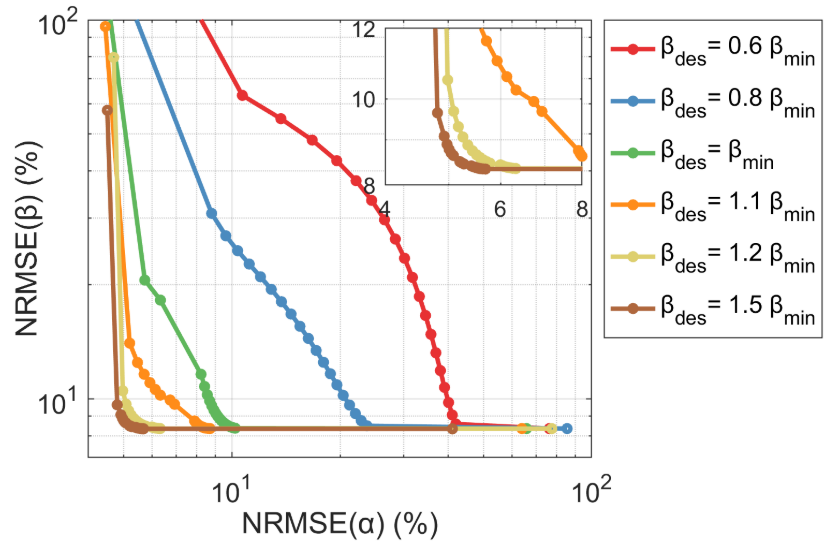
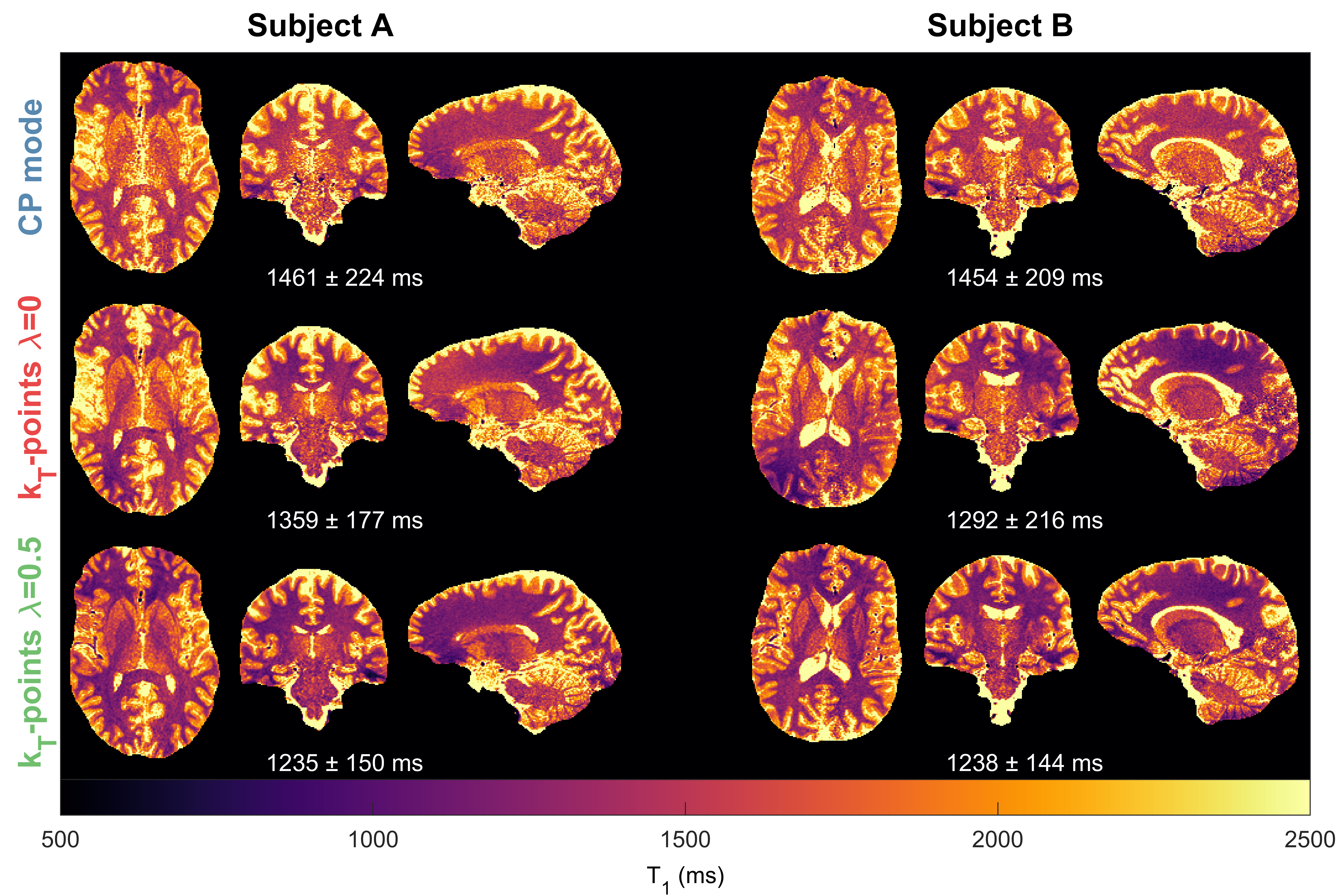
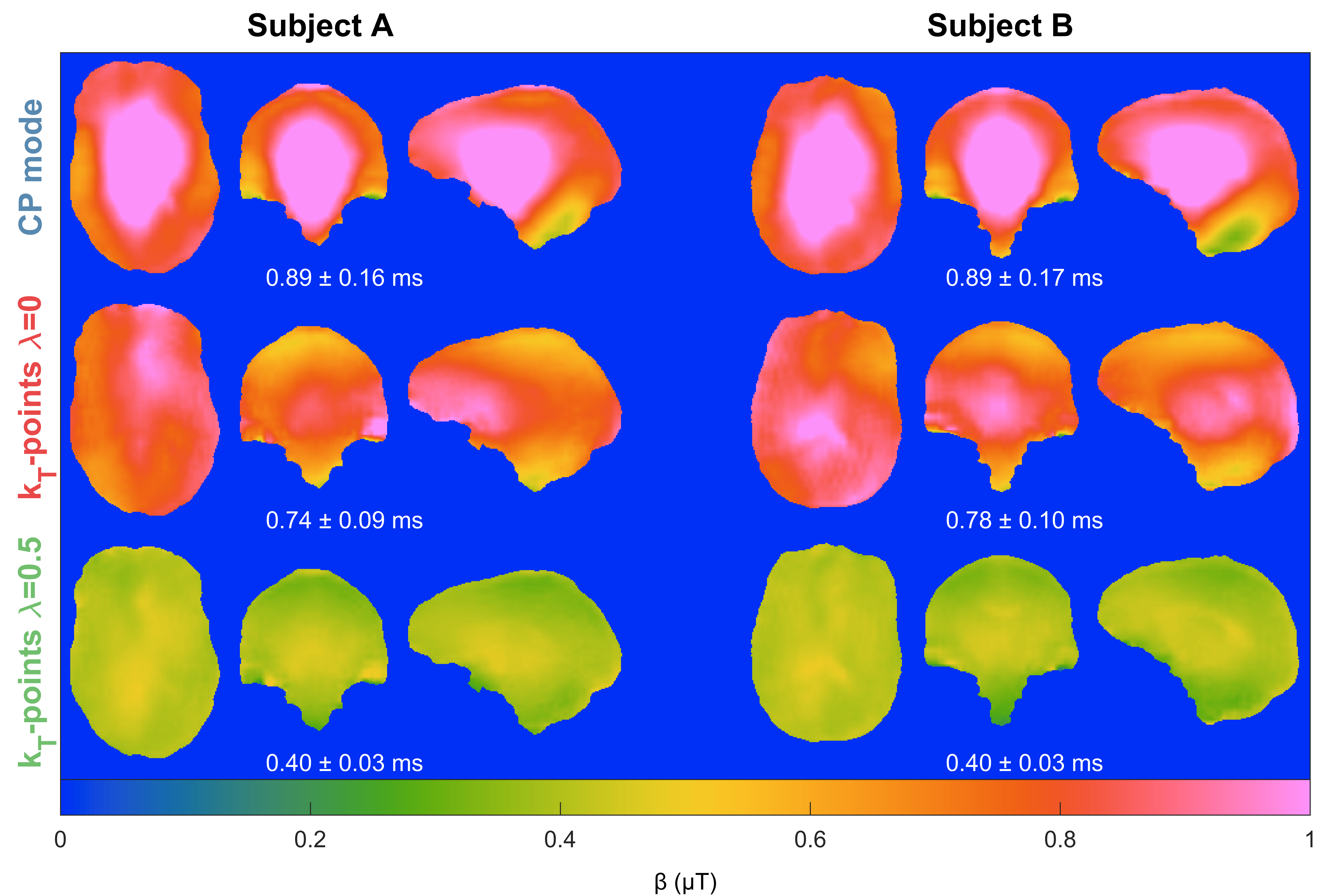
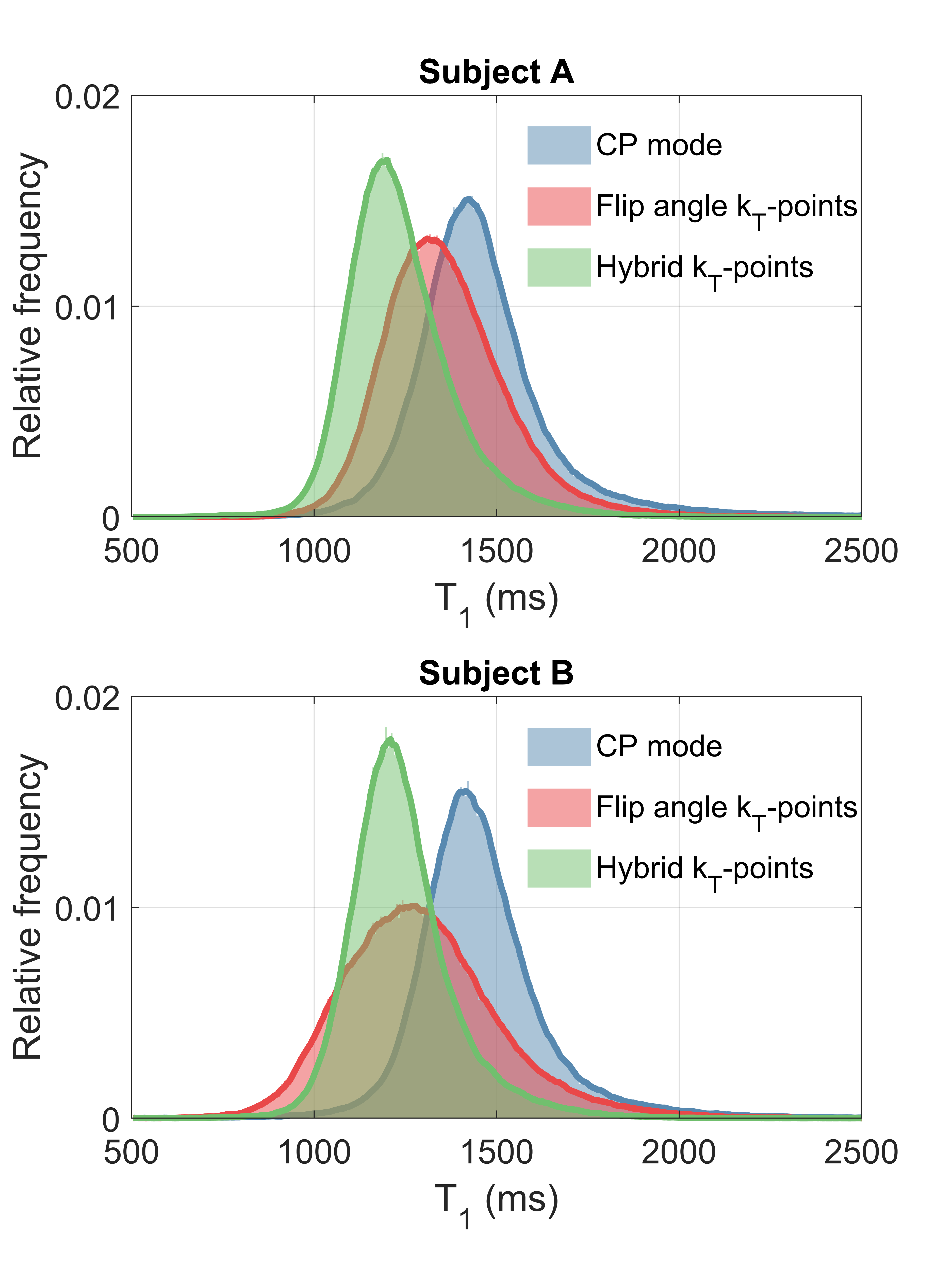
Figure 1 shows the Pareto front when changing $$$\lambda$$$ for different targets $$$\mathrm{\beta_{des}}$$$. This resembles an L-curve with most solutions in the corner when $$$\mathrm{\beta_{des}\geq\beta_{min}}$$$. The in-vivo $$$\mathrm{\hat{T}_1}$$$ maps in Figure 2 show that CP mode yields a similar pattern in both subjects with longer towards the middle of the brain and a noisier estimation. With flip angle optimized ($$$\lambda=0$$$) kT-points the estimation is more precise (less noisy), however there is a stronger variation of across space that is different for each subject. For the hybrid optimized kT-points ($$$\lambda=0.5$$$) the $$$\mathrm{\hat{T}_1}$$$ is spatially more uniform and consistent for both subjects. These patterns correlate with the respective $$$\mathrm{B_1^{rms}}$$$ maps for the $$$12^\circ$$$ pulse in Figure 3, where larger $$$\mathrm{B_1^{rms}}$$$ leads to longer $$$\mathrm{\hat{T}_1}$$$. Moreover, whilst flip angle optimized kT-points leads to different $$$\mathrm{B_1^{rms}}$$$ maps across subjects, the hybrid optimized kT-points yields consistent and more uniform $$$\mathrm{B_1^{rms}}$$$ maps. Figure 4 confirms that $$$\mathrm{\hat{T}_1}$$$ values in WM have the smallest dispersion when using hybrid optimized kT-points, whereas using flip angle optimized kT-points lead to a bigger dispersion compared to CP mode (after correcting for flip angle).Discussion and Conclusion
The proposed pulse design is a generalization of a ‘standard’ flip angle optimization and a ‘PUSH’ optimization4. Simulations showed that solutions are mostly independent of the choice of $$$\lambda$$$ if $$$\mathrm{\beta_{des}\geq\beta_{min}}$$$, meaning that it is possible to obtain simultaneously uniform flip angle and $$$\mathrm{B_1^{rms}}$$$. Observed $$$\mathrm{T_1}$$$ values changed considerably depending on the pulse type applied. Whilst flip angle inhomogeneities can be corrected during fitting, changes in $$$\mathrm{B_1^{rms}}$$$ (Figure 3) lead to $$$\mathrm{\hat{T}_1}$$$ bias. Therefore, while flip angle optimized kT-points helps mitigate the impact of $$$\mathrm{B_1^+}$$$ inhomogeneity on the excitation, it yields unpredictable $$$\mathrm{B_1^{rms}}$$$ distributions that can create highly heterogeneous semisolid saturation leading to spatially non-uniform $$$\mathrm{\hat{T}_1}$$$. On the other hand, hybrid optimized kT-points controls the $$$\mathrm{B_1^{rms}}$$$ distribution and yielded more uniform $$$\mathrm{\hat{T}_1}$$$ maps, resulting in narrower distributions of $$$\mathrm{\hat{T}_1}$$$ in white matter (Figure 4).Acknowledgements
The research was funded/supported by core funding from the Wellcome/EPSRC Centre for Medical Engineering [WT203148/Z/16/Z] and by the National Institute for Health Research (NIHR) Biomedical Research Centre based at Guy's and St Thomas' NHS Foundation Trust and King's College London and/or the NIHR Clinical Research Facility. The views expressed are those of the author(s) and not necessarily those of the NHS, the NIHR or the Department of Health and Social Care.References
1. Hoult, D. I. & Phil, D. Sensitivity and power deposition in a high-field imaging experiment. Journal of Magnetic Resonance Imaging 12, 46–67 (2000).
2. Katscher, U., Börnert, P., Leussler, C. & van den Brink, J. S. Transmit SENSE. Magn Reson Med 49, 144–150 (2003).
3. Setsompop, K., Wald, L. L., Alagappan, V., Gagoski, B. A. & Adalsteinsson, E. Magnitude least squares optimization for parallel radio frequency excitation design demonstrated at 7 tesla with eight channels. Magn Reson Med 59, 908–915 (2008).
4. Leitão, D. et al. Parallel transmit PUlse design for Saturation Homogeneity (PUSH) for Magnetization Transfer imaging at 7T. Magn Reson Med 88, 180–194 (2022).
5. Ou, X. & Gochberg, D. F. MT effects and T1 quantification in single-slice spoiled gradient echo imaging. Magn Reson Med 59, 835–845 (2008).
6. Teixeira, R. P. A. G., Malik, S. J. & Hajnal, J. v. Fast quantitative MRI using controlled saturation magnetization transfer. Magn Reson Med 81, 907–920 (2019).
7. van Gelderen, P., Jiang, X. & Duyn, J. H. Effects of magnetization transfer on T1 contrast in human brain white matter. Neuroimage (2016) doi:10.1016/j.neuroimage.2015.12.032.
8. Christensen, K. A., Grant, D. M., Schulman, E. M. & Walling, C. Optimal determination of relaxation times of Fourier transform nuclear magnetic resonance. Determination of spin-lattice relaxation times in chemically polarized species. Journal of Physical Chemistry 78, 1971–1976 (1974).
9. Yarnykh, V. L. Actual flip-angle imaging in the pulsed steady state: A method for rapid three-dimensional mapping of the transmitted radiofrequency field. Magn Reson Med 57, 192–200 (2007).
10. Padormo, F. et al. Large dynamic range relative B1+ mapping. Magn Reson Med 76, 490–499 (2016).
11. Baudrexel, S., Nöth, U., Schüre, J. R. & Deichmann, R. T1 mapping with the variable flip angle technique: A simple correction for insufficient spoiling of transverse magnetization. Magn Reson Med 79, 3082–3092 (2018).
Figures