0201
Validation and Application of SLfRank RF Pulse Design1Radiology, Stanford University, Palo Alto, CA, United States, 2Radiology, Stanford University, Stanford, CA, United States, 3University of California Santa Barbara, Santa Barbara, CA, United States, 4Electrical Engineering, Stanford University, Stanford, CA, United States
Synopsis
Keywords: RF Pulse Design & Fields, RF Pulse Design & Fields
SLfRank is a novel RF pulse design framework proposed to improve upon the well-established Shinnar Le-Roux (SLR) design algorithm. Numerical experiments demonstrated promising effectiveness of SLfRank, prompting a need to validate its experimental feasibility. An experimental comparison of SLR and SLfRank is achieved by measuring slice profiles, multiband excitation, and spin-echo pulses on phantom and human brain. SLfRank produced images of comparable quality to the SLR algorithm, but with reduced RF energy and greater control over RF pulse phase. SLfRank’s numerical feasibility aligned closely with its effectiveness experimentally thus proving its technical feasibility for applications in this work and beyond.Introduction
The Shinnar-Le-Roux (SLR) algorithm1 is a widely used technique to design frequency selective pulses, especially with large flip angles that can address the high nonlinearity of the Bloch Equation. By mapping RF pulses to pairs of polynomials that represent Cayley-Klein (CK) parameters, it vastly simplified the RF pulse design problem into a finite impulse response (FIR) filter design problem. Because the CK polynomial pair is bi-linearly coupled, the original SLR algorithm sequentially solves for each polynomial instead of jointly, resulting in sub-optimal pulses. Recently, an improved SLR Pulse Design framework using Rank Factorization, known as SLfRank, was proposed2. The new algorithm converted the bi-linear problem into a convex problem that can simultaneously estimate the two pairs of CK parameters, which leads to reduced energy and more accurate phase control of the RF pulse. However, only numerical experiments have been performed using the novel algorithm. The practical feasibility of SLfRank has not been verified yet. Therefore, the purpose of this study is to provide evidence of the technical feasibility of SLfRank through measuring the slice profile, and exploring two potential applications in multiband excitation and single-shot FSE.Methods
SLR v.s. SLfRank:The conventional SLR algorithm sequentially solves each CK polynomial with energy constraints whereas SLfRank solves the two polynomials jointly by constructing a convex problem. Concretely, define:
$$\mathbf{\psi}(z)=\begin{pmatrix}1&z&\ldots&z^{n-1}\end{pmatrix}^T,\\\mathbf{a}=\begin{pmatrix}a_{n,0}&a_{n,1}&\ldots & a_{n,n-1}\end{pmatrix}^T,\\\mathbf{b}=\begin{pmatrix}b_{n,0}&b_{n,1}&\ldots & b_{n,n-1}\end{pmatrix}^T$$
where $$$z=e^{i \omega}=e^{i \gamma GX\Delta t}$$$.
Then all the energy constraints can be represented using the outer product of the CK polynomial coefficients P:
$$\mathbf{P}=\begin{pmatrix}\mathbf{P}_{aa}&\mathbf{P}_{ab}\\\mathbf{P}_{ba} & \mathbf{P}_{bb} \\ \end{pmatrix}=\begin{pmatrix}\mathbf{a}\\\mathbf{b}\end{pmatrix}\begin{pmatrix}\mathbf{a}^*&\mathbf{b}^*\end{pmatrix}$$
By relaxing the rank-one constraint into a positive semi-definite matrix constraint:
$$\mathbf{P}\succeq\begin{pmatrix}\mathbf{a}\\\mathbf{b}\end{pmatrix}\begin{pmatrix}\mathbf{a}^*&\mathbf{b}^*\end{pmatrix}$$
A convex problem can thus be constructed. Using the properties of the Schur complement, it is equivalent to:
$$\mathbf{X}=\begin{pmatrix}1&\mathbf{a}^*&\mathbf{b}^*\\\mathbf{a}&\mathbf{P}_{aa}&\mathbf{P}_{ab}\\\mathbf{b}&\mathbf{P}_{ba}&\mathbf{P}_{bb}\\\end{pmatrix}\succeq0.$$
Similar to the original SLR algorithm, $$$a_{n,0}$$$ is maximized to minimize pulse energy and $$$b_{n, 0}$$$ is maximized to generate minimum phase pulses.
Slice Profile Measurement
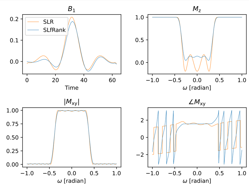
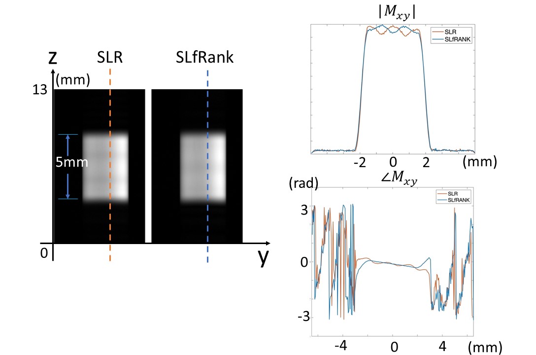
The slice profile of the linear phase excitation pulse was first measured on a water phantom. The design parameters used for both SLR and SLfRank were time-bandwidth (TBW) = 8, maximum absolute errors=1%, n=64 and pulse width=2.0ms. The experiment was performed on a GE 3T scanner with a 32-channel head coil, using a custom-built GRE sequence by changing the frequency-encoding gradient to slice-selection direction. The slice profile was also compared with numerical results.
Multi-band Excitation
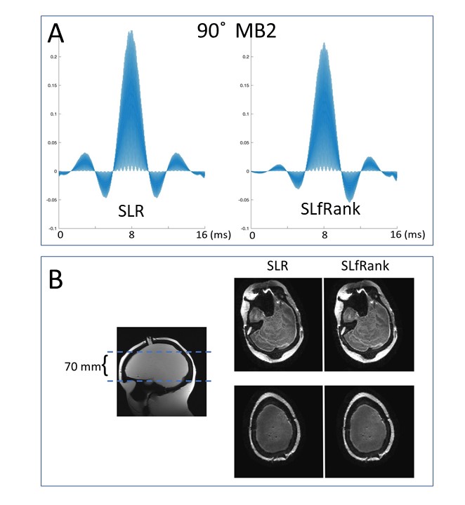
The second experiment was to design and test a multi-band excitation pulse using SLfRank on a brain water phantom. Specifically, the RF pulse was designed with a multi-band factor of 2, slice thickness of 2 mm and 70 mm apart. The RF pulse length was 16ms, which was then incorporated into a spin-echo EPI sequence. Key parameters of the acquisition were: TR=4000ms, TE=72.7ms, FOV=220×220mm2, matrix=110×110, slice thickness=2mm, 35 slices. The acquired data was reconstructed using SENSE with the sensitivity map acquired from a separate low-resolution GRE sequence.
Spin-echo Pulse in SSFSE
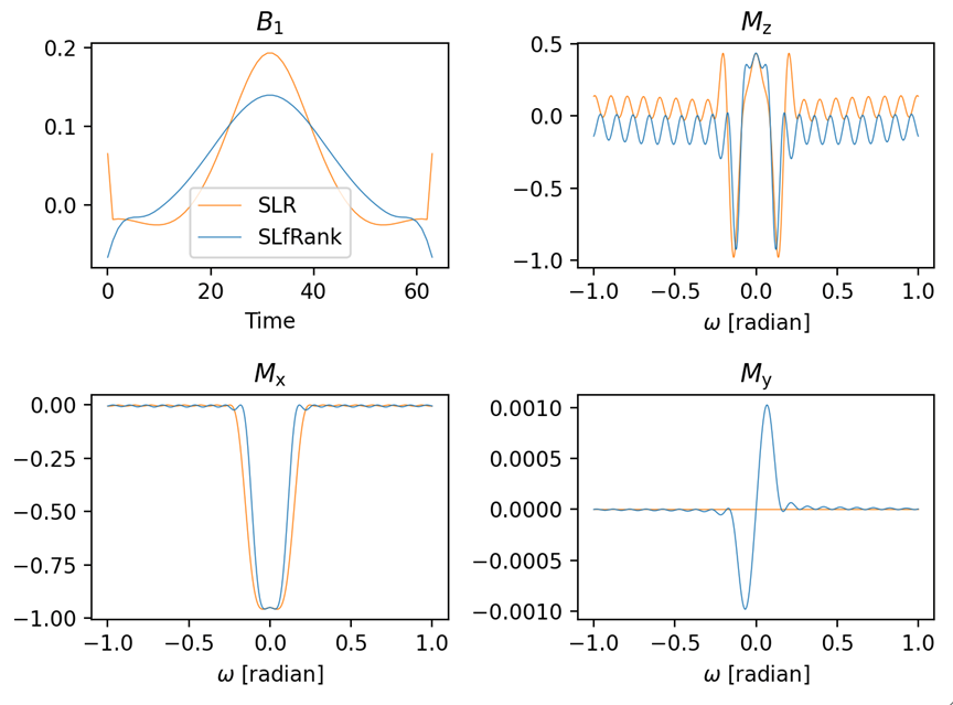
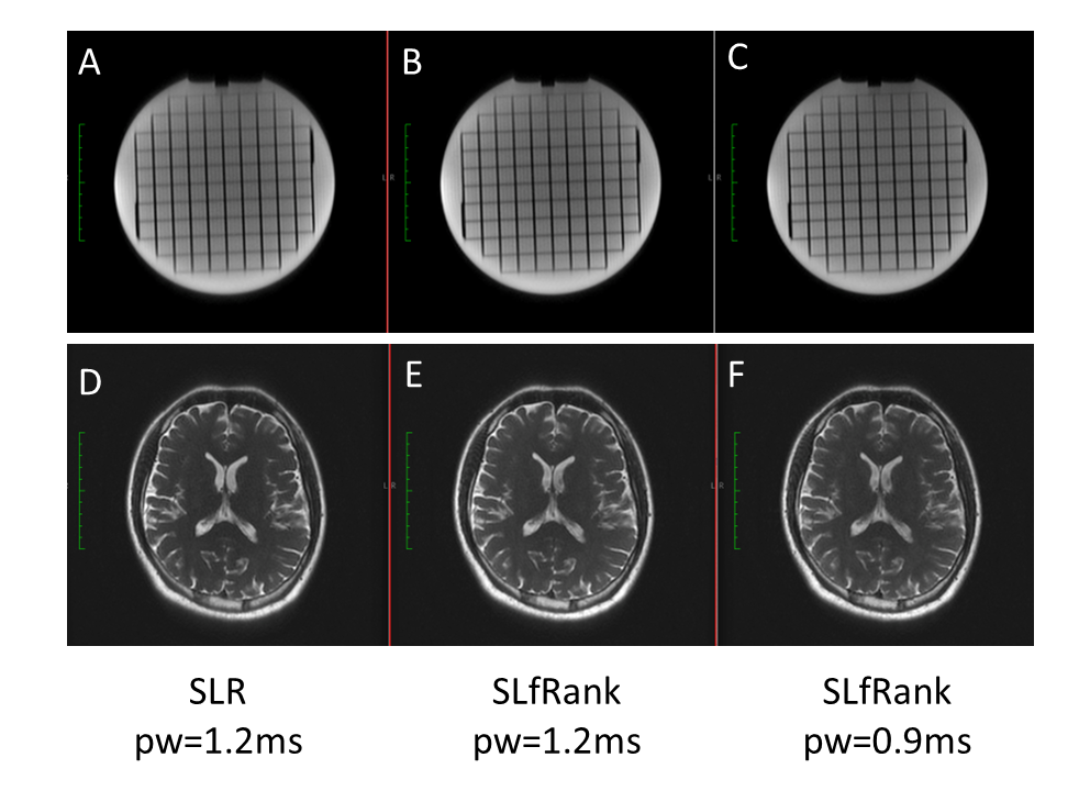
The third experiment was to design a linear phase spin-echo pulse and incorporated into a single-shot FSE (SSFSE) sequence to acquire water phantom and brain images. The RF pulse design parameters were: TBW=3, flip angle=155 degrees, maximum absolute errors=1%, and pulse width=1.2ms. The key sequence parameters of SSFSE acquisition were: TR=550ms, TE=90 ms, acceleration factor=2, slice thickness=3mm, acquisition matrix=256×224. As a comparison, the experiment was repeated with a shortened SLfRank pulse of 0.9ms, corresponding to a minimum TR of 430ms.
Results
Figure 1 shows the numerical results of a linear phase excitation pulse designed using SLR and SLfRank, respectively. The measured slice profile matched well with the numerical results (Figure 2). Note the phase response of SLfRank pulse is more linear than SLR, demonstrating that the proposed design compensates for the phase of α in order to generate a linear phase profile.Figure 3A is the multiband RF pulse designed using SLR and SLfRank, respectively. Compared with the conventional SLR pulse, SLfRank has a 19 % energy reduction and lower peak B1 with similar image quality (Figure 3B).
Figure 4 is the numerical results of a spin-echo pulse designed using SLR and SLfRank, respectively. Both water phantom and human brain images showed similar quality (Figure 5). More importantly, the SSFSE using shorter SLfRank pulse reduced the acquisition time by 21.8%.
Discussion and Conclusion
The technical feasibility of the novel SLfRank framework was successfully validated through the slice profile measurement and two applications (multi-band excitation and SSFSE).One key advantage of SLfRank over SLR is the optimized RF energy, as seen through numerical and experimental validations. The reduced energy can be readily translated to reduce the acquisition time, such as a 21.8% acquisition reduction in SSFSE. Another advantage of SLfRank is the more accurate control of the RF pulse phase, as evidenced by the flatter phase response measured in the slice profile experiment. This can be particularly useful for designing RF pulses with quadratic phase and multiband pulse which requires more accurate phase control. Root flipping is another potential exploration direction, where the peak RF amplitude can be further reduced. More applications can be further explored beyond this work and the discussions above.
In conclusion, SLfRank could be a drop-in replacement for SLR in most applications with less energy and more accurate phase control.
Acknowledgements
This work was supported in part by Stanford Center for Pediatric IBD and Celiac Disease Research Training Award, NIH R01EB009690 and NIH U01EB029427, and GE Healthcare.References
1. Pauly, J., Le Roux, P., Nishimura, D. & Macovski, A. Parameter relations for the Shinnar-Le Roux selective excitation pulse design algorithm (NMR imaging). IEEE Trans. Med. Imaging 10, 53–65 (1991).
2. Ong, F. et al. SLfRank: Shinnar-Le-Roux Pulse Design with Reduced Energy and Accurate Phase Profiles using Rank Factorization. Preprint at http://arxiv.org/abs/2103.07629 (2022).
3. Positive trigonometric polynomials and signal processing applications. (Springer Berlin Heidelberg, 2017).
4. Pipe, J. G. Spatial Encoding and Reconstruction in MRI with Quadratic Phase Profiles. Magn. Reson. Med. 33, 24–33 (1995).
5. Setsompop, K. et al. Improving diffusion MRI using simultaneous multi-slice echo planar imaging. NeuroImage 63, 569–580 (2012).
6. Sharma, A., Lustig, M. & Grissom, W. A. Root-flipped multiband refocusing pulses: Root-Flipped Multiband Refocusing Pulses. Magn. Reson. Med. 75, 227–237 (2016).
Figures