0200
Multidimensional RF pulse design in spin-domain using auto-differentiation for 3D refocusing pulse
Jiayao Yang1, Jon-Fredrik Nielsen2, and Yun Jiang2,3
1Department of Electrical Engineering and Computer Science, University of Michigan, Ann Arbor, MI, United States, 2Department of Biomedical Engineering, University of Michigan, Ann Arbor, MI, United States, 3Department of Radiology, University of Michigan, Ann Arbor, MI, United States
1Department of Electrical Engineering and Computer Science, University of Michigan, Ann Arbor, MI, United States, 2Department of Biomedical Engineering, University of Michigan, Ann Arbor, MI, United States, 3Department of Radiology, University of Michigan, Ann Arbor, MI, United States
Synopsis
Keywords: RF Pulse Design & Fields, RF Pulse Design & Fields
This study proposed a novel algorithm for designing multidimensional RF in spin-domain using auto-differentiation in PyTorch. Our algorithm uses spin-domain description of rotations to formulate the RF pulse design into optimization problems. We designed 3D refocusing pulses and verified the performance using spin-echo based sequences in phantom at 1.5T and in vivo in the brain at 3T.Introduction
The goal of this study is to develop an RF pulse design algorithm in spin-domain for a 3D refocusing pulse used in reduced field-of-view (rFOV) imaging. rFOV imaging techniques excite inner volume to reduce the encoding burden for higher spatial resolution or faster acquisition, compared to the imaging technique for the full FOV. While spin-echo based rFOV imaging can be achieved by using orthogonal RF excitation1 or 2D spatially-selective RF pulse2,3, a 3D spatially-selective refocusing pulse could potentially further reduce the encoding burden. However, to design a 3D tailored refocusing pulse is challenging due to the large flip angle when most RF pulse design algorithms use small-tip approximation4. While recent work5 using an auto-differentiable Bloch simulation demonstrated its potential to design pulses with large flip angles, the objective function using the Bloch equation in designing a refocusing pulse is complicated to formulate by specifying the initial and desired magnetization pattern.In this study, we propose an algorithm to design multidimensional RF pulses in the spin-domain using the auto-differentiable simulation. We exploit the spin-domain description of rotations to efficiently formulate the refocusing pulse design problem without implicitly specifying the initial magnetization.
Methods
In the spin-domain, the rotation of the magnetization is described by Cayley-Klein parameters $$$\alpha$$$ and $$$\beta$$$, which are complex parameters and can be used to describe the functions of different pulses. The refocusing pulse can be designed by requiring: 1) $$$|\beta^2| = 1$$$ for the refocusing region; 2) $$$\beta^2$$$ have the same phase within the refocusing region.In this study, We designed RF pulses over a 30x30x30cm3 using a matrix with size of 40x40x40 to target certain ROIs for different experiments. We formulated our RF design as an optimization problem in terms of $$$\beta$$$ using l1 norm: $$\begin{aligned}\mathop{\arg\min}_{\boldsymbol{b},\boldsymbol{g}} \mathcal{L} = \sum_{i=1}^{N} w_i |\beta_{S,i}^2(\boldsymbol{b},\boldsymbol{g}) - \beta_{D,i}^2|, \\ \text{s.t.} \quad \text{hardware limits}\end{aligned}$$ where $$$\boldsymbol{b}$$$ is a matrix of size $$$2\times N_t$$$ representing the RF waveform, $$$\boldsymbol{g}$$$ is a matrix of size $$$3\times N_t$$$ representing the gradient waveforms, and $$$N_t$$$ is the number of timepoints used. $$$N$$$ is the number of spins of different locations, $$$\beta_{S,i}^2$$$ is the simulation result for spin $$$i$$$, $$$\beta_{D,i}^2$$$ is the desired pattern for spin $$$i$$$, and $$$w_i$$$ is the weights assigned to that spin. Our algorithm was constrained by the hardware limitations of the MRI scanner, such as peak B1 of 25 uT, gradient strength of 50 mT/m, and slew rate of 120mT/m/s.
Our simulation for $$$\alpha$$$ and $$$\beta$$$ used the hard pulse approximation with dwell time of 4us. We implemented the optimization using auto-differentiation in PyTorch, which provides the derivative for optimization and makes the computation fast especially when the number of spins are relatively large in our design. We treated $$$\alpha$$$ and $$$\beta$$$ with their real and imaginary components to avoid directly computing the derivative of complex numbers.
Our design started by initializing the RF and gradient using the joint design method for small-tip 3D tailored excitation6. Then we jointly optimized the RF and gradient using an alternating scheme: 1) update RF using Frank-Wolfe method; 2) update gradient waveform based on gradient descent with constrained step size. During the update of RF and gradient waveform, we re-estimate desired pattern $$$\beta_{D,i}^2$$$ in the objective by computing the average of simulated $$$\beta_{S,i}^2$$$ within the ROI then scaling the magnitude to 1. This strategy leads to a faster decrease of the objective function.
To evaluate the performance of our algorithm, we replaced SINC refocusing pulse by our 3D refocusing pulse in both 2D and 3D spin-echo sequences implemented in Pulseq7. The phantom experiment was performed at Siemens 1.5T with an RF pulse designed to refocus the region of 10x10x5cm3, and in vivo brain imaging was performed at Siemens 3T with a refocusing region of 7x7x6cm3.
Results
Figure 1 shows a comparison of initial input excitation pulse and optimized output refocusing pulse. A visible change on the RF waveform is produced by our algorithm, and the change of gradient waveform can be noticed from their k-space trajectories. Figure 2 shows a comparison of $$$\beta^2$$$ pattern for initial and optimized refocusing pulse based on our simulation. It can be seen that optimized $$$\beta^2$$$ within the ROI have magnitudes close to 1 and have the same phase. Figure 3 shows 2D images acquired in phantom. We compared images acquired with 300x300mm3 with and without 3D refocusing RF pulse, and small FOV=150x150mm2 using 3D refocusing RF pulse. Figure 4 shows 3D spin-echo images in phantom at 1.5T with reduced FOV=150x150x70mm3. We also performed experiments in vivo in the brain at 3T. Figure 5 shows these acquired 2D and 3D SE images. This demonstrates our 3D refocusing pulse can allow acquisition of reduced FOV.Conclusion and Discussion
In this study, we developed a novel algorithm for designing multidimensional RF pulses in spin-domain using auto-differentiation in PyTorch. Our results show the rFOV images can be acquired using our designed refocusing pulse, demonstrating the proposed algorithm provides an efficient way to design 3D refocusing RF pulse. While focusing on the design of the refocusing pulse in this study, our algorithm can also be applied in designing various RF pulses, such as excitation, saturation, and inversion pulses.Acknowledgements
We receive research support from Siemens Healthineers, NIH grant R01CA208236 and R37CA263583.References
- Mansfield, P., R. J. Ordidge, and R. Coxon. "Zonally magnified EPI in real time by NMR." Journal of Physics E: Scientific Instruments 21.3 (1988): 275.
- Rieseberg, Susanne, Jens Frahm, and Jürgen Finsterbusch. "Two‐dimensional spatially‐selective RF excitation pulses in echo‐planar imaging." Magnetic Resonance in Medicine: An Official Journal of the International Society for Magnetic Resonance in Medicine 47.6 (2002): 1186-1193.
- Saritas, Emine Ulku, et al. "DWI of the spinal cord with reduced FOV single‐shot EPI." Magnetic Resonance in Medicine: An Official Journal of the International Society for Magnetic Resonance in Medicine 60.2 (2008): 468-473.
- Pauly, John, Dwight Nishimura, and Albert Macovski. "A k-space analysis of small-tip-angle excitation." Journal of Magnetic Resonance (1969) 81.1 (1989): 43-56.
- Luo, Tianrui, et al. "Joint Design of RF and gradient waveforms via auto-differentiation for 3D tailored excitation in MRI." IEEE Transactions on Medical Imaging 40.12 (2021): 3305-3314.
- Hao, Sun, et al. "Joint design of excitation k-space trajectory and RF pulse for small-tip 3D tailored excitation in MRI." IEEE transactions on medical imaging 35.2 (2015): 468-479.
- Layton, Kelvin J., et al. "Pulseq: a rapid and hardware‐independent pulse sequence prototyping framework." Magnetic resonance in medicine 77.4 (2017): 1544-1552.
Figures
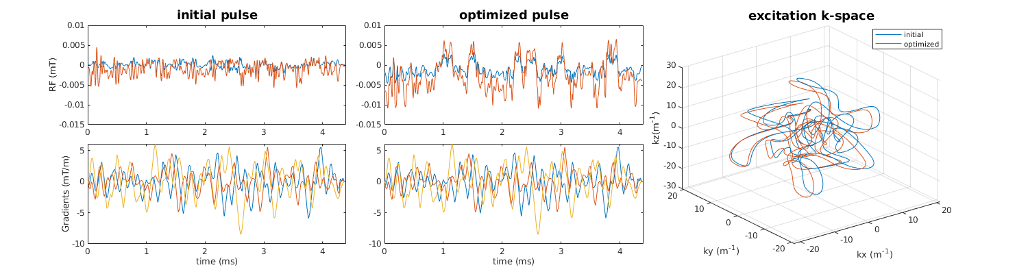
Figure 1: Comparison of initial 3D excitation pulse and optimized 3D refocusing pulse. The pulse duration is 4.38ms. The optimized RF waveform has changed a lot from the initial. The gradient waveform is also changed by looking at the excitation k-space trajectory.
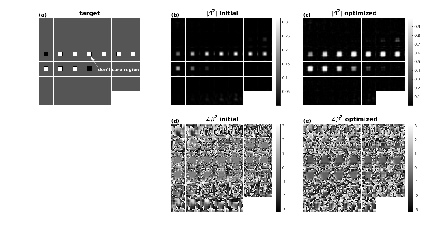
Figure 2: (a) shows an aimed refocusing region of size 7x7x6cm3 with 0.4cm transition region. (b) and (d) show the initial magnitude and phase of $$$\beta^2$$$. (c) shows the magnitude of optimized $$$\beta^2$$$ of 3D refocusing pulse is close to 1 within ROI. (e) shows that the optimized phase of $$$\beta^2$$$ are smooth within ROI. This indicates the magnetization within ROI will be refocused around the same axis.
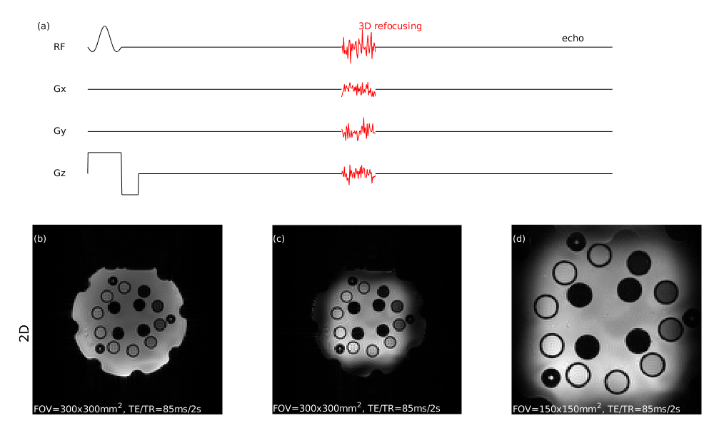
Figure 3: (a) illustrates the spin-echo sequence with replacement of the 3D refocusing pulse. (b-d) show 2D SE images with 90° SINC excitation for a 5mm slice. (b) uses SINC refocusing pulse and acquired with FOV=300x300mm2. (c) use 3D refocusing pulse and acquired with FOV=300x300mm2. (d) also uses 3D refocusing pulse but with FOV=150x150mm2.

Figure 4: 3D SE images using the designed 3D refocusing pulse in phantom. The excitation is 10cm slice and aimed refocusing region is 10x10x5cm3 . The acquired image is with FOV=150x150x70mm3 and acquisition is 128x40x20 in k-space.
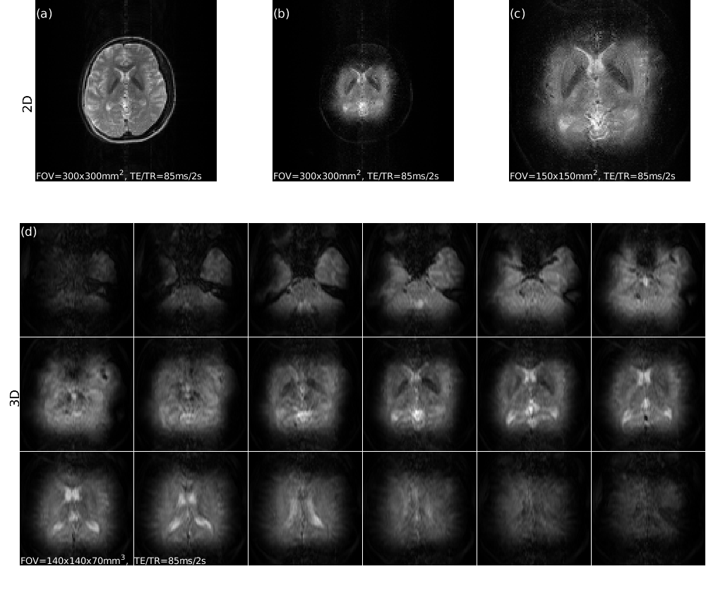
Figure 5: (a-c) are 2D SE images of the brain with 5mm-excitation, the aimed refocusing region of 3D refocusing pulse is 7x7x6cm3. (a) uses SINC refocusing with FOV=300x300mm2. (b) uses 3D refocusing pulse with FOV=300x300mm2. (c) uses 3D refocusing pulse but FOV=150x15mm2. (d) is 3D SE images with 10cm-excitation and 3D refocusing pulse, FOV=140x140x70mm3, acquisition is 128x40x18 in k-space.
DOI: https://doi.org/10.58530/2023/0200