0199
Universal pulses for the cervical spinal cord at 7T: a feasibility study1NeuroPoly Lab, Institute of Biomedical Engineering, Polytechnique Montreal, Montreal, QC, Canada, 2University of Paris-Saclay, CEA, NeuroSpin, CNRS, BAOBAB, Gif sur Yvette, France, 3Siemens Healthcare SAS, Saint-Denis, France, 4Mila - Quebec AI Institute, Montreal, QC, Canada, 5Functional Neuroimaging Unit, Centre de recherche de l'Institut universitaire de gériatrie de Montréal, Montreal, QC, Canada, 6Centre de recherche du CHU Sainte-Justine, Université de Montréal, Montreal, QC, Canada
Synopsis
Keywords: Parallel Transmit & Multiband, Spinal Cord
While the Universal Pulse approach to mitigate the RF field inhomogeneity effect has been successfully deployed in brain imaging, adoption in spinal cord imaging is lacking. Here, we demonstrate the feasibility of designing Universal Pulses for the cervical spinal cord at 7T, and show a marked improvement for signal intensity in the upper thoracic cord.Introduction
For high-field MRI, the Universal Pulse (UP) approach[1] offers a solution to mitigate B1+ homogeneity of parallel-transmit systems, without the need for lengthy, patient-specific RF pulse calculations and calibration. While the UP approach has been successfully deployed for brain[1] and cardiac[2] imaging, applications to spinal cord imaging have been lacking so far. Here, we demonstrate for the first time the feasibility of designing UPs for the cervical and upper thoracic spinal cord at 7T.Methods
Database acquisitions:Six volunteers (age 23-45, 5M, 1F) were scanned to build up a database of B0 and B1+ maps for pulse design. Scans were acquired using a custom-built 8Tx/20Rx cervical spinal cord array[3], and Siemens 7T Terra system. B0 maps were acquired using a triple-echo sequence, while B1+ maps were acquired using the XFL sequence in interferometric mode[4]. Volunteers were positioned and trained according to established guidelines[5]. All maps were acquired in axial orientation, 72 slices, 4mm thickness and in-plane resolution of 1.5x1.5mm. The FOV was centered at the C3/C4 disc, and covered at least C1-T4 for all volunteers. A rectangular B0 shim volume covering the spinal cord was used for all acquisitions.
Database construction:
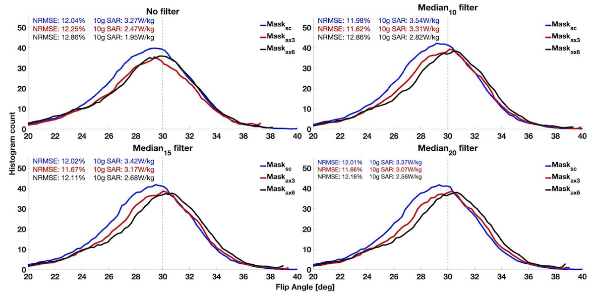
A combination of smoothing kernels and masks were applied to the six pairs of B0 and B1+ maps to evaluate the sensitivity of the designed UPs to these factors. First, the maps were either not smoothed (no filter), or smoothed with a median filter of 10mm (median10), 15mm (median15) or 20mm (median20) length. Next, the maps were masked. The spinal cord was segmented from the magnitude scan of the B0 maps using Spinal Cord Toolbox[6], and three masks were derived: a spinal cord mask without padding in the axial plane (MaskSC), a mask with 3mm padding in the axial plane (Maskax3), and a mask with 6mm padding in the axial plane (Maskax6). In total, 12 databases were constructed: {MaskSC,no filter}, {MaskSC,median10}, {MaskSC,median15}, {MaskSC,median20},{Maskax3,no filter}, {Maskax3,median10}, {Maskax3,median15}, {Maskax3,median20},{Maskax6,no filter},{Maskax6,median10}, {Maskax6,median15}, {Maskax6,median20}.
For each dataset, a UP with 30° nominal FA and 800 µs duration was calculated (UPAFI). Global/10g SAR limits were 3.2W/kg and 20 W/kg and were enforced by using home-made VOPs, and maximum power per Tx-channel was 3W. For simplicity, Universal Pulses were calculated in RF shimming mode, without k-T points. This pulse was then simulated on one of the six volunteers (43, M) to evaluate the effect of masking and filtering. The 10g maximum SAR of the designed pulse, and the normalized root mean square error (NRMSE) of the simulated FA compared to the nominal, were computed.
In-vivo evaluation:
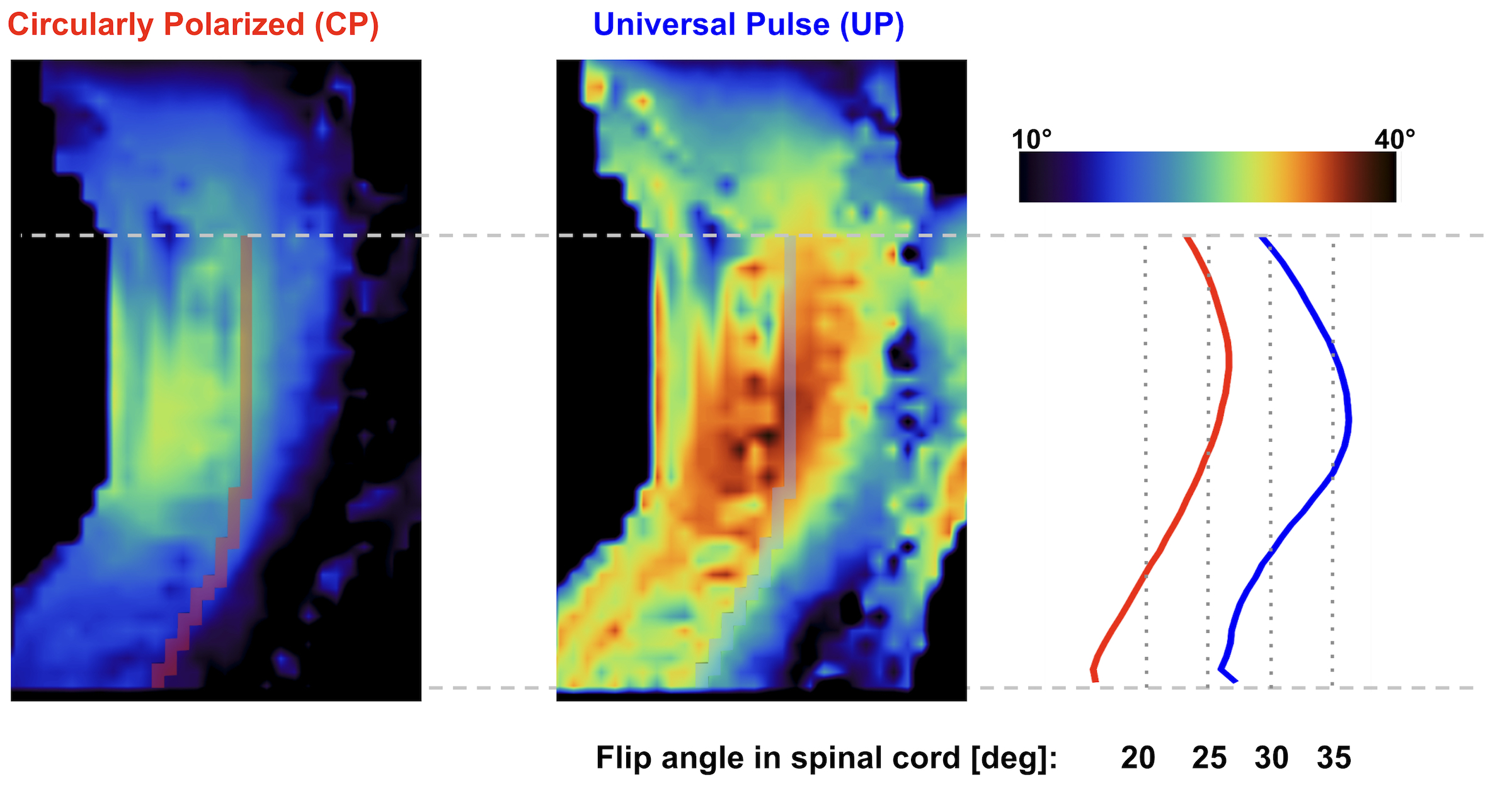
An additional volunteer (27, M) was scanned using two UPs, both designed on the {MaskSC, no filter} database as it gave the most reliable results. A 3D GRE scan with 1mm isotropic resolution, TR/TE=25/3ms and a nominal FA of 15° was acquired with and without UP excitation. FOV positioning and coverage was as previously described. In order to directly measure the flip angle distribution, an AFI scan of 4mm isotropic resolution was acquired, using the UPAFI pulse with 30° nominal FA, with an FOV covering C1-T2.
Results
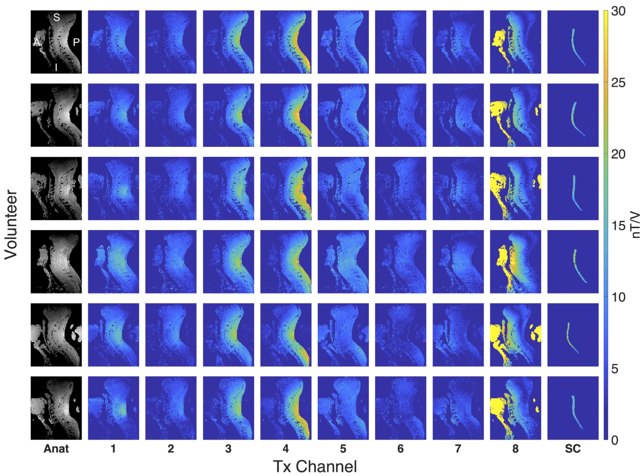
Database construction:B1+ maps of the database are shown in Figure 1. The six volunteers exhibit noticeable variation in spinal cord curvature, despite careful positioning and training.
Masking and filtering:
Figure 2 shows the effect of masking and filtering on the resulting simulated flip angle distribution after Bloch simulation of the UPs. Broader masks result in a slightly increased flip angle, but neither masking nor filtering have a strong effect on the FA distribution. As a trend, for a given filter, broader masks lead to a decrease in the 10g SAR of the simulated pulse, at the cost of increasing the NRMSE.
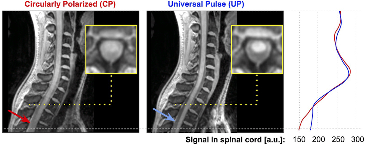
GRE signal intensity:
The signal intensity of the GRE scans acquired with and without UP is shown in Figure 3. UP excitation results in a more homogeneous signal, particularly in the anterior-inferior direction, and greatly improves the contrast between SC and CSF and improves SC signal in the thoracic region.
AFI B1+ mapping:
Shown in Figure 4, UPs markedly increased the achieved flip angle. In CP mode, the flip angle along the spinal cord is only ~20°, compared to ~30° using UP excitation. UP excitation resulted in a reduction of NRMSE from 27% to 17%. Coefficient of variation along the spinal cord was reduced from 15% in CP mode to 10% with UP.
Discussion and conclusion
We have successfully demonstrated the feasibility of designing UPs for the spinal cord at 7T. Even with a small design database of only six subjects, UP excitation was found to improve homogeneity of GRE signal along the SC by increasing signal intensity along the thoracic cord. Within the thoracic cord, contrast between SC and CSF was poor in CP mode, but improved using UP excitation. Notably, these improvements were achieved without time-consuming calibration during scan time.Future work will focus on expanding the database of B0/B1+ maps to include a broader range of age, sex, and anatomical variability, as well as designing Universal Pulses with more advanced pulse designs to achieve even lower NRMSEs for clinically applicable sequences such as MP2RAGE.
Acknowledgements
Funded by the Canada Research Chair in Quantitative Magnetic Resonance Imaging [950-230815], the Canadian Institute of Health Research [CIHR FDN-143263], the Canada Foundation for Innovation [32454, 34824], the Fonds de Recherche du Québec - Santé [28826], the Natural Sciences and Engineering Research Council of Canada [RGPIN-2019-07244], the Canada First Research Excellence Fund (IVADO and TransMedTech), the Courtois NeuroMod project and the Quebec BioImaging Network [5886, 35450], and MITACS Accelerate Fellowship, and European Union’s H2020 research and innovation programme under grant agreement 885876 (AROMA).References
1. Gras V, Vignaud A, Amadon A. Universal pulses: a new concept for calibration‐free parallel transmission. Magn Reson Med. 2017 Feb;77(2):635-643. doi: 10.1002/mrm.26148.
2. Aigner CS, Dietrich S, Schaeter T, Schmitter S. Calibration-free pTx of the human heart at 7T via 3D universal pulses. Magn Reson Med. 2022 Jan;87(1):70-84. doi: 10.1002/mrm.28952
3. Lopez Rios N, Topfer R, Foias A, Guittonneau A, Gilbert KM, Menon RS, Wald LL., Sotckmann JP., Cohen-Adad J. Integrated AC/DC coil and dipole Tx array for 7T MRI of the spinal cord. Proc. Intl. Soc. Mag. Reson. Med. 27 (2019)
4. Amadon A, Mauconduit F, Vignaud A, Boulant N. Slice profile corrections in the XFL (magnetization-prepared turbo-FLASH) B1-mapping sequence. Proc. Intl. Soc. Mag. Reson. Med. 23 (2015)
5. Cohen-Adad J, Alonso-Ortiz E, Abramovic M, Arneitz C, Atcheson N, Barlow L, et al. Generic acquisition protocol for quantitative MRI of the spinal cord. at Protoc. 2021 Oct;16(10):4611-4632. doi: 10.1038/s41596-021-00588-0
6. De Leener B, Lévy S, Dupont SM, Fonov VS, Stikov N, Louis Collins D, Callot V, Cohen-Adad J. SCT: Spinal Cord Toolbox, an open-source software for processing spinal cord MRI data. Neuroimage. 2017;145: 24–43.
Figures