RF Transmit Chain: Amplification, Power Transfer, B1 Control and SAR
1National Institutes of Health, United States
Synopsis
In this lecture, I will review design principles, implementation, and control of the radiofrequency (RF) hardware that generates the excitation B1 field in MRI scanners of various B0 field strengths.
Introduction
Despite the direct dependence of the B1 transmit field on the coil current, most Tx coils used in MRI are controlled by voltage signals. Like in traditional radio communication systems, power is transmitted from the radiofrequency power amplifier (RFPA) to the coil terminal through a 50 Ω coaxial connection. Thus, maximum power transfer to the coil is possible through impedance matching at the different stages in the chain. One or more RF pulses are only applied during a small fraction of the MRI pulse sequence repetition time, therefore the RFPA operates in pulsed-mode instead of continuous-mode. The output power required from the RFPA increases as we move to higher magnetic fields, not only because the energy necessary to resonate the nuclear spins in the tissue increases with B02, but also because cable and circuit losses increase with frequency. Nowadays we have access to human ultra-high field (UHF) MRI systems (> 7 T) designed to achieve higher signal-to-noise-ratio (SNR), spatial resolution and signal contrast. At these fields, the B1 generated by a single channel volume Tx coil is distorted due to interaction of the shorter excitation wavelength (λRF) with the human body. B1 corrections are possible through the implementation of a multiple channel Tx coil array. This array can be controlled with maximum flexibility when the amplitude, phase, and shape of the RF pulse per channel can be changed dynamically and independently. This method is known as parallel transmission (pTx). Besides the increased complexity of the hardware and control, a major challenge in the implementation of this technology for routine MRI is ensuring RF safety for all combinations of pulse excitations and coil-patient setups. A review on the engineering and physics concepts involved in the design and implementation of the single and parallel Tx chains will be presented.RF Power
In MRI the flip angle excitation depends on the amplitude and duration of the applied B1 field. For a short (<1 ms) inversion pulse (180° flip angle) a B1+ >12 μT should be generated by the Tx coil. The required power to generate this B1 amplitude depends on the amount of power absorbed by the electrically conductive sample (of conductivity σ and permittivity ε) and power losses in the Tx chain and coil. Typically, a whole-body coil transmit efficiency is in the order of tenths $$$\mu$$$T$$$\sqrt{W}$$$, demanding tens of kW of pulsed power from the RFPA. Most RFPAs installed in commercial MRI systems are voltage quasi-linear amplifiers (Class AB). This amplifier topology presents low to medium power efficiency (< 60%) because, despite its pulse-mode operation, it is continuously driving DC current. Consequently, amplifiers are assembled on large water cooled heatsinks and located in the equipment room remote from the coil. RFPA specifications are high power/voltage gain, good linearity, and power efficiency. This allows the generation of kilowatt RF pulses with good fidelity of the small RF pulse signal set by the control.Single Channel Tx Chain
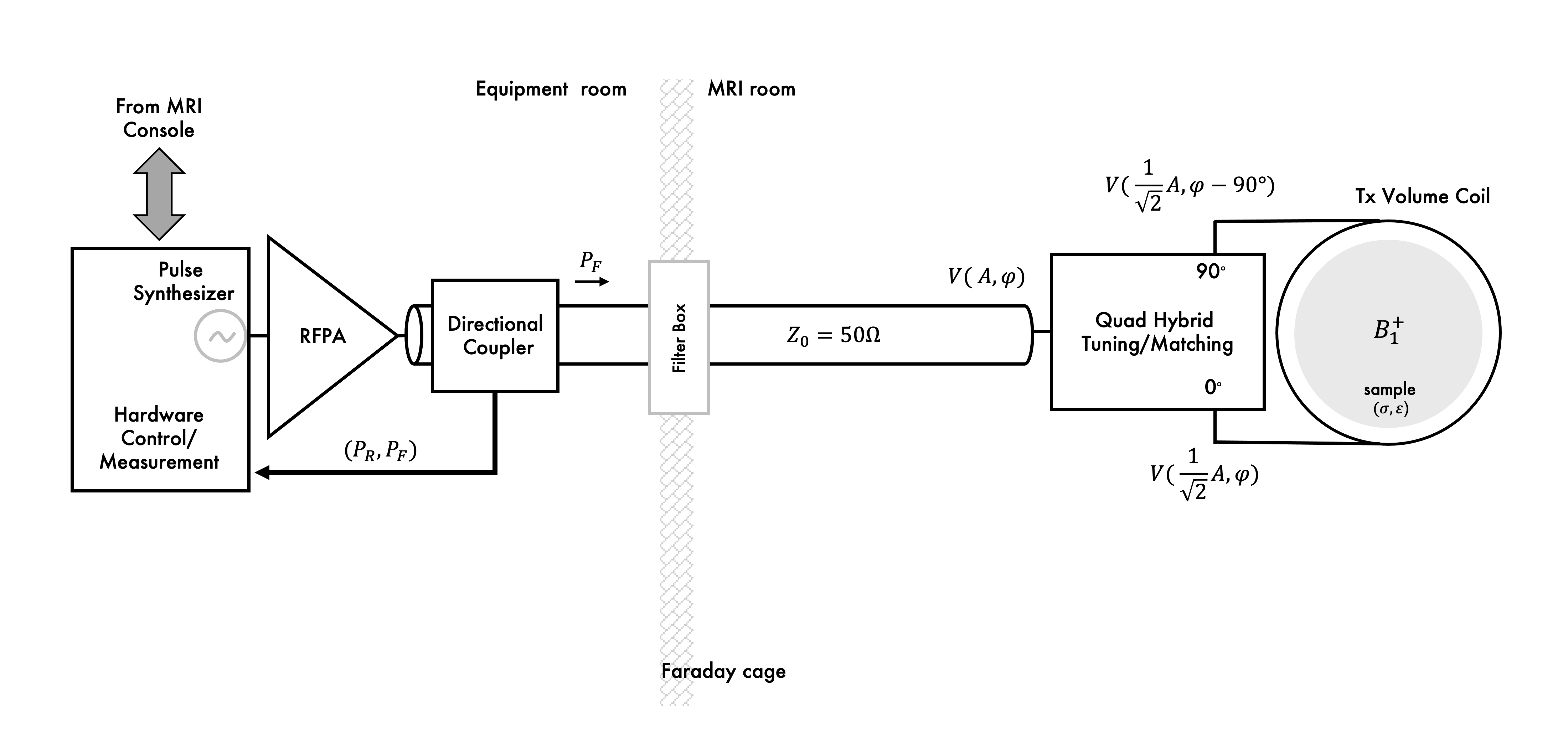
In most MRI setups, RF power generated by the RFPA is delivered to the sample by a Tx volume coil. Example of a single channel Tx chain implementation is shown Figure 1. Power is transferred to the volume coil (e.g., a birdcage transmitter) through a Q-hybrid (operating as 2-way 90° power splitter) which generates two quadrature voltages to drive two ports located at a 90° azimuthal angle. Each of these voltages is maximized at the ports through a 50 Ω matching network and power delivered to the coil can be monitored through a directional coupler. A Tx volume coil generates a circularly polarized (CP) B1 field rotating at the excitation frequency (Larmor frequency). For most imaging applications at MRI fields up to 3 T, a CP B1 field generates a very uniform transverse magnetization profile across the sample (λRF>sample dimensions). This is important to acquire clinically valuable tissue contrast information. Thus, a large Tx volume coil, known as body coil, is normally integrated in the scanner bore of MRI scanners up to 3 T. However, at this field strength degraded performance of the volume excitation may be observed in imaging of the abdomen. To improve this, independent control of the 2-port transmitter was implemented in clinical systems to add flexibility to shim the B1 field in a selected region of interest (ROI). At UHF MRI, B1 homogeneity can be severely compromised, and higher number of independently controlled Tx channels are necessary for correction.Parallel Channel Tx Chain
Multiple-channel transmitter consists of an array of coils (e.g. surface loops), each generating a linearly polarized (LP) B1 field that can be independently controlled (parallel transmission system) to generate different excitation modes (e.g. including a CP or gradient mode). This flexibility can be used to shim the B1 field at high and ultra-high field. In an ideal multi-channel transmit setup, total transmit power is given by the sum of power delivery per element (e.g. loop coil, strip line or dipole antenna). Therefore, the most common approach to drive a multi-channel Tx array is to scale down the power and replicate the conventional Tx chain (Fig. 2). This is a straightforward approach that rely on the same Tx hardware concepts broadly used in MRI. In this setup, elements of the array can be decoupled by capacitive, inductive or geometric (element overlapping or separation) decoupling methods. A well decoupled (< -15 dB isolation between channels) 50 Ω matched Tx array driven by the conventional Tx chain allows for independent and power efficient control per channel. With higher number of channels, higher is the complexity of tuning, matching, and decoupling of coil elements and cables to achieve good Tx performance. To reduce this complexity, new RFPA architectures were presented to allow its relocation in the chain for near or on-coil power amplification(1–4).Multi-Nuclear Tx Chain
In addition to the 1H Tx chain, MRI scanners can have a lower-frequency x-nuclei Tx chain. In this chain, power is normally generated by a broadband instead of a narrowband RF amplifier. As in the 1H Tx chain, this amplifier is voltage-mode linear or quasi-linear amplifier with bandwidth across all x-nuclei frequencies of interest. This chain can drive a single or multiple tuned x-nuclei surface, volume, or array coil. Depending on the coil configuration (e.g., multiple-tuned or nested single tuned coil, volume or array coil, Tx only or Tx-Rx coils) the multi-nuclear setup can have multiple layers of coils concentrically arranged(5). In this multi-layer coil arrangement, a challenge is to minimize element coupling and losses to achieve good Tx efficiency at each frequency. Usually, 1H Tx efficiency is compromised to get better efficiency for the lower sensitivity x-nuclei. Analogous to the multi-channel Tx setup, the multi-nuclear Tx setup requires replication of the Tx chain. Here; however, each Tx channel operates at a different x-nucleus resonant frequency. Therefore, the complexity of coaxial connections, coil interfaces and decoupling networks increases with the number of x-nuclei to be excited in a single experiment. Power deposition and losses are reduced at the lower frequencies, therefore less power is required from the x-nuclei broadband RFPA than that required from the 1H narrowband RFPA. Since B1 homogeneity is better at the lower frequencies, most multi-nuclear excitations are performed with a Tx volume coil. As we move to higher B0 fields, B1 homogeneity is degraded even for the lower-frequency x-nuclei. Therefore, a multi-channel approach may be adopted for the lower frequency x-nuclei excitation. Because of the many tuning and matching tasks that result from replication of the 50 Ω coaxial Tx chain, a multi-channel, multi-nuclear Tx setup using this approach can be cumbersome.B1 Control
The B1 field distribution depends on the coil geometry (and surrounding structures) and the sample. Prior to an MRI scan, an automatic or manual Tx power adjustment is performed while measuring the flip angle at the scanner isocenter. In a single Tx mode, a single voltage signal is adjusted to control B1 amplitude. In a pTx setup this calibration requires the adjustment of the voltage (or current) amplitude and phase per channel. To assess pTx performance we can measure the B1 field in the MRI experiment. Several methods have been developed for fast in vivo B1 mapping(6–9). After an initial calibration, the pTx setup offers the flexibility to optimize the B1 distribution in a selected ROI. This is possible by dedicated pTx pulse sequences that allow dynamic control of the amplitude, phase and even the shape of the RF pulse per channel. From Faraday’s law, we know that the time varying B1 field generates a time varying E1 field which we cannot “see” in MRI. Because the amplitude and phase per channel are controlled to optimize B1 across the sample, the resulting total E1 distribution can present local maxima that cause excessive heating in the tissue. To perform B1 optimization constrained by safety parameters, optimization algorithms were developed for the automated control of signal amplitude and phase per channel(10–13).SAR Control
During a MRI scan, every time an RF pulse is transmitted, power is deposited in the tissue ($$$\propto$$$E12). Over time this can heat the tissue, so RF pulse amplitude and duty cycle are restricted. Restrictions are based on measurements of local and global power deposition per unit mass of tissue defined as specific absorption rate (SAR) in W/kg. Local and global SAR thresholds for whole body and different body extremities are specified in safety standards (e.g., IEC 60601-2-33). Clinical MRI scanners operate in a restricted SAR mode. Any sequence that attempts to go beyond a SAR limit will be halted by the control. To have comfortable safety margins, SAR is normally overestimated in clinical MRI scanners. But an overly restrictive system may result in underperformance of the Tx hardware and pulse sequence. Modifications to the Tx chain for more accurate power monitoring have been driven mainly by SAR control in pTx systems. Non-magnetic directional couplers located closer to the coil terminals(14) or magnetically coupled current sensors (15-17) have been implemented for real time measurement of Tx signal amplitude and phase per channel. This not only allows better estimation of global SAR, but also helps in the calculation of local SAR using electromagnetic field simulations. New technologies for RF signal monitoring and control(18–21) in combination with fast mapping of the B1 field can be used to acquire subject-specific SAR predictions for safe pTx operation.Discussion
Most recent modifications to the RF transmit chain have been mainly driven by the implementation of pTx arrays at ultra-high field. New hardware and software have been developed to control and monitor the transmit power per channel. Nowadays, most pTx systems are built using a scaled version of the conventional Tx chain. However, transmit efficiency and control of a pTx array can be improved by the design of a dedicated Tx chain. A better control of the B1 field per channel can be achieved through a current source excitation(1, 3, 22), instead of the traditional voltage source. Moving the amplifier closer to the coil facilitates the reduction of losses and coupling of coaxial connections. Complete elimination of these issues is possible by direct connection of the amplifier to the coil which allows replacing coaxial cables by optical fibers(3, 4). In addition, simplification of the coil array can be achieved by eliminating decoupling networks using active decoupling methods such as feedback(19, 20) or amplifier decoupling(1, 3, 21, 22) .Acknowledgements
No acknowledgement found.References
1. Kurpad KN, Wright SM, Boskamp EB: RF current element design for independent control of current amplitude and phase in transmit phased arrays. Concepts Magn Reson 2006; 29B:75–83.
2. Heilman JA, Riffe MJ, Heid O, Griswold MA: High Power,High Efficiency On-Coil current mode amplifier for Parallel Transmission Arrays. In Proceedings of the 15th ISMRM, Berlin, Germany; 2007:171.
3. Gudino N, Heilman JA, Riffe MJ, Heid O, Vester M, Griswold MA: On-coil multiple channel transmit system based on class-D amplification and pre-amplification with current amplitude feedback. Magn Reson Med 2013; 70:276–289.
4. Gudino N, Duan Q, de Zwart JA, et al.: Optically controlled switch-mode current-source amplifiers for on-coil implementation in high-field parallel transmission. Magn Reson Med 2016; 76:340–349.
5. Brown R, Lakshmanan K, Madelin G, Parasoglou P: A nested phosphorus and proton coil array for brain magnetic resonance imaging and spectroscopy. Neuroimage 2016; 124(Pt A):602–611.
6. Dowell NG, Tofts PS: Fast, accurate, and precise mapping of the RF field in vivo using the 180 degrees signal null. Magn Reson Med 2007; 58:622–630.
7. Jiru F, Klose U: Fast 3D radiofrequency field mapping using echo-planar imaging. Magn Reson Med 2006; 56:1375–1379.
8. Sacolick LI, Wiesinger F, Hancu I, Vogel MW: B1 mapping by Bloch-Siegert shift. Magn Reson Med 2010; 63:1315–1322.
9. Yarnykh VL: Actual flip-angle imaging in the pulsed steady state: a method for rapid three-dimensional mapping of the transmitted radiofrequency field. Magn Reson Med 2007; 57:192–200.
10. Mahmood Z, Guerin B, Adalsteinsson E, Wald LL, Daniel L: An Automated Framework to Decouple pTx Arrays with Many Channels. In In Proceedings of the 21st Annual Meeting ISMRM, Salt Lake City, USA; 2013:2722.
11. Alon, Leeor, Deniz, CM, Lattanzi, R, et al.: An Automated Method for Subject Specific Global SAR Prediction in Parallel Transmission. In Proc Intl Soc Mag Reson Med 18; 2010:780.
12. Lee J, Gebhardt M, Wald LL, Adalsteinsson E: Local SAR in parallel transmission pulse design. Magn Reson Med 2012; 67:1566–1578.
13. Eichfelder G, Gebhardt M: Local specific absorption rate control for parallel transmission by virtual observation points. Magn Reson Med 2011; 66:1468–1476.
14. El-Sharkawy A-MM, Qian D, Bottomley PA, Edelstein WA: A multichannel, real-time MRI RF power monitor for independent SAR determination. Med Phys 2012; 39:2334–2341.
15. Graesslin I, Biederer S, Falaggis, K, et al.: Real-time SAR Monitoring to ensure Patient Safety for Parallel Transmission Systems. In Proc Intl Soc Mag Reson Med 15; 2007:1086.
16. Gagosky B, Hamm M, Setsompop K: Real time RF monitoring in a 7T parallel transmit system. Stockholm, Sweden; 2010:781.
17. Hoult DI, Kolansky G, Kripiakevich D, King SB: The NMR multi-transmit phased array: a Cartesian feedback approach. Journal of Magnetic Resonance 2004; 171:64–70.
18. Hoult DI, Kolansky G, Kripiakevich D, King SB: The NMR multi-transmit phased array: a Cartesian feedback approach. J Magn Reson 2004; 171:64–70.
19. Scott GC, Stang P, Kerr A, Pauly J: General Signal Vector Decoupling for Transmit Arrays. In Proceedings of the 16th ISMRM,Toronto, Ontario, Canada; 2008:146.
20. Stang P, Kerr A, Scott GC: An Extensible Transmit Array System using Vector Modulation and Measurement. In Proc Intl Soc Mag Reson Med 16; 2008:145.
21. Gudino N, de Zwart JA, Duan Q, et al.: Optically controlled on-coil amplifier with RF monitoring feedback. Magn Reson Med 2018; 79:2833–2841.
22. Lee W, Boskamp E, Grist T, Kurpad K: Radiofrequency current source (RFCS) drive and decoupling technique for parallel transmit arrays using a high-power metal oxide semiconductor field-effect transistor (MOSFET). Magn Reson Med 2009; 62:218–228.
Figures