5048
Comparison of simulated parallel transmit head arrays at 7T using excitation uniformity, local SAR, and global SAR
Ehsan Kazemivalipour1,2, Lawrence L. Wald1,2,3, and Bastien Guerin1,2
1A.A. Martinos Center for Biomedical Imaging, Department of Radiology, Massachusetts General Hospital, Charlestown, MA, United States, 2Harvard Medical School, Boston, MA, United States, 3Harvard-MIT Division of Health Sciences Technology, Cambridge, MA, United States
1A.A. Martinos Center for Biomedical Imaging, Department of Radiology, Massachusetts General Hospital, Charlestown, MA, United States, 2Harvard Medical School, Boston, MA, United States, 3Harvard-MIT Division of Health Sciences Technology, Cambridge, MA, United States
Synopsis
We investigate the performance of parallel transmission arrays with 8, 16, 24, and 32 channels and varying loop sizes (18 coils total) for brain imaging at 7T. We compare RF-shimming performance of the arrays using the L-curve method showing optimal tradeoffs between excitation uniformity (slice), local-SAR, global-SAR and peak-power. For the numbers of channels simulated here, the coils with larger loops achieved a better local-SAR vs. excitation uniformity than those with smaller loops (this was true for axial/sagittal slice orientations). At constant local-SAR constraint, the 24-channel arrays showed the best performance in improving the excitation uniformity in the coronal/axial slices.
Introduction
Parallel transmission (pTx) allows control of the magnetization and the E-field/specific absorption rate (SAR)1,2. This is especially impactful at 7T, where pTx can be used to create uniform excitation profiles and reduce local-SAR. The added transmit degrees of freedom (DoF) provided by pTx pulses and coils depends in a complex manner on the number of the transmit channels, the size of the channels, and their position with respect to the head. Ideally, optimal operating points need to be compared for different coil designs, which requires solving a pulse-design problem with explicit constraints for the variables being assessed. Since we are interested in the excitation uniformity and local-SAR, this means that local-SAR needs to be constrained explicitly in the pulse-design problem. Here, we take a practical approach to pTx coil optimization by electromagnetic simulation and RF-shimming pulse-design of pTx coils with 8, 16, 24, and 32 channels with varying loop diameters.Methods
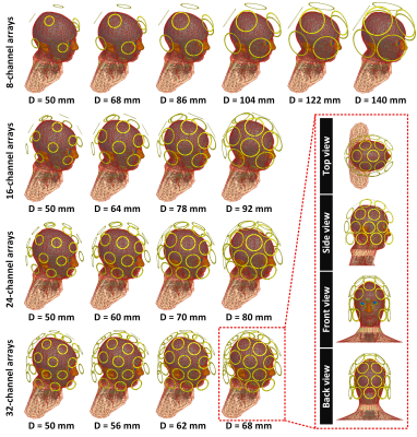
We simulated the 18 pTx arrays for head imaging at 7T shown in Fig.1. For each coil, the loops are placed on an elliptic former with a hemi-ellipsoid top-end that approaches the shapes used in closed-fitting helmets. The loop locations were optimized by minimization of the maximum Euclidean distance between loop centers (feasible since the former surface is an analytical formula). At constant number of channels, we evaluated the impact of varying the loop diameter (all loops have the same diameter in this study). The smallest loop diameter considered was 50mm and the maximum was the one resulting in contact between nearest-neighbors (for the 8-channel Dmax=70mm, 16-channel Dmax=46mm, 24-channel Dmax=40mm, and 32-channel Dmax=34mm). Each array was loaded with a detailed human head model (with shoulders, 22 tissues3,4). Simulations and circuit co-simulations were performed with ANSYS Electronics by replacing all sources and capacitors with lumped ports. The multiport S-matrix output of HFSS was imported into MATLAB, where we used custom code to find the tuning/matching capacitor values for each coil design. Generation of the coil models, tuning, matching and export of the field results was done in batch mode using MATLAB (HFSS can be controlled externally by MATLAB), thus allowing to efficiently simulate a large number of coil designs.We extracted B1+-maps and E-fields on a 191×121×171, 2mm isotropic image grid (we did not attempt decoupling of the nearest-neighbors) and computed 10g-averaged SAR-matrices (Q-matrices) for each voxel5,6, which we then compressed using the virtual observation points (VOPs)7. We designed slice-selective RF-shimming pulses (target flip-angle of 10°) in central axial/coronal/sagittal brain slices. Each pulse was a 5-lobe sinc profile of 2ms duration, duty-cycle of 100%, and slice thickness of 5mm. The pulses were designed using least-squares optimization for a zero-target phase2,8 subject to a fixed peak-power constraint (56.25W/channel). L-curves were obtained by varying local-SAR constraints (global-SAR was not constrained).
Results
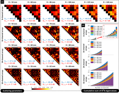
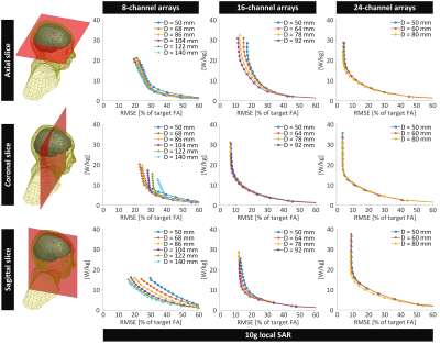
Fig.2A shows the S-matrices for the tuned and matched coils (natural coupling). The matching level was better than -35dB for all arrays. Increasing the number of array elements or the loop diameter led to an increase in the maximum coupling. Greater coupling is associated with greater eigenvalues of the SHS-matrix (power-matrix)9, indicating greater reflected power of the eigenmode excitations (Fig.2B).Figs.3-5 show the shim performance of the array designs. For the 8-channel array (and, to some extent the 16-channel), increasing the loops diameter improved the excitation uniformity vs. local-SAR tradeoff for the transverse/sagittal designs. However, for the coronal slice, increasing the loop diameter did not necessarily improve the imaging performance, and, for the 8-channel coils, even created lower-quality excitations at the lower local-SAR range of values studied.
Fig.5 shows that increasing the channel count from 8 to 16 and then to 24 improved the pulse performance for the axial/coronal slices, while increasing the number of channels from 24 to 32 did not always improve transmit performance further. In some cases, it even worsened it, indicating that for some slice orientations, the 24-channel coil has more effective DoFs than the 32-channel coil. This can be due to the specifics of the coil DoFs projected on the slice of interest and to increased coupling in the 32-channel coil that reduces the effective transmit DoFs.
Conclusion and Discussion
This simulation study shows that pTx coil comparison depends on the pulse-design strategy and is highly non-linear, with some L-curves crossing even when using a convex pulse-design strategy (least-squares)8,10. As expected, increasing the number of channels generally led to better transmit performance (local-SAR vs. excitation uniformity) in the moderate-high local-SAR regime, although this simple conclusion was not always true at lower SAR values (16-channel sometimes outperform 24- and 32-channel). Increasing the loop diameter (at constant number of channels) led to better transmit performance for the 8-channel coil only, and only for the transverse/sagittal slice orientations (for the coronal slice orientation, the performance initially increased with D, then decreased). In next steps, we will vary individual loop diameters. Although more complex, this may actually lead to a simpler ranking and conclusions since we would be in essence comparing optimal coil configurations (or close to optimal) for varying number of channels. The MATLAB-based simulation/tuning/matching/pulse design strategy used here will make it easier to run through the hundreds of simulations required for that goal.Acknowledgements
No acknowledgement found.References
- Katscher U, Bornert P, Leussler C, et al. Transmit SENSE. Magn Reson Med. 2003;49(1):144-150.
- Zhu Y. Parallel excitation with an array of transmit coils. Magn Reson Med. 2004;51(4):775-784.
- Massire A, Cloos MA, Luong M, et al. Thermal simulations in the human head for high field MRI using parallel transmission. J Magn Reson Imaging. 2012;35(6):1312-1321.
- Makris N, Angelone L, Tulloch S, et al. MRI-based anatomical model of the human head for specific absorption rate mapping. Med Biol Eng Comput. 2008;46(12):1239-1251.
- Sbrizzi A, Hoogduin H, Lagendijk JJ, et al. Fast design of local N-gram-specific absorption rate-optimized radiofrequency pulses for parallel transmit systems. Magn Reson Med. 2012;67(3):824-834.
- Das SK, Clegg ST, Samulski TV. Computational techniques for fast hyperthermia temperature optimization. Med Phys. 1999;26(2):319-328.
- Eichfelder G, Gebhardt M. Local specific absorption rate control for parallel transmission by virtual observation points. Magn Reson Med. 2011;66(5):1468-1476.
- Guerin B, Gebhardt M, Cauley S, et al. Local specific absorption rate (SAR), global SAR, transmitter power, and excitation accuracy trade-offs in low flip-angle parallel transmit pulse design. Magn Reson Med. 2014;71(4):1446-1457.
- Kazemivalipour E, Sadeghi-Tarakameh A, Atalar E. Eigenmode analysis of the scattering matrix for the design of MRI transmit array coils. Magn Reson Med. 2021;85(3):1727-1741.
- Wu
X, Zhang X, Tian J, et al. Comparison of RF body coils for MRI at 3 T: a simulation
study using parallel transmission on various anatomical targets. NMR Biomed.
2015;28(10):1332-1344.
Figures

Figure 1 – Simulated 7T parallel transmit (pTx) head
loop arrays loaded with a detailed human head and shoulders model. The arrays were
simulated in 8-channel, 16-channel, 24-channel, and 32-channel configurations. The array elements were 5 mm wide copper loops
broken by 3 tuning capacitors regularly distributed along their circumferences.

Figure 2 – (A) Scattering parameters of the simulated pTx
arrays at 297 MHz. For each coil, the maximum reflection coefficient (in blue)
and couplings (in red) were also shown. (B) The cumulative sum of the square of
the singular values of the S-parameters (the eigenvalues of SHS9) for each coil. These eigenvalues indicate a measure
of the normalized reflected power for different eigenmode excitations (the
eigenvectors of SHS). The eigenmodes with higher reflection have higher eigenvalues.

Figure
3 – L-curves for least-squares RF-shimming
(maximum 10g-averaged local SAR vs. excitation error) for the 8-, 16-, and
24-channel array designs in the central axial, coronal, and sagittal brain slices
when the peak-power on each channel was constrained to 56.25 W.

Figure
4 - L-curves for least-squares RF-shimming
(global SAR vs. excitation error) for the 8-, 16-, and 24-channel array designs
in the central axial, coronal, and sagittal brain slices when the local SAR
constraint was varied as shown in Figure 3. The peak-power on each channel was
also constrained to 56.25 W.

Figure
5 – L-curves for least-squares RF-shimming
(maximum 10g-averaged local SAR vs. excitation error) for the 8-, 16-, and
24-channel array designs with their smallest loop diameters (first row) and
their largest loop diameters (second row) in the central axial, coronal, and
sagittal brain slices when the peak-power on each channel was constrained to
56.25 W.
DOI: https://doi.org/10.58530/2022/5048