5047
In Scan Room No-Interference High Efficiency Switching Power Supply with GaN
Juan A Sabate1, Logan A Snow1, Huan A Hu1, and Randy Buchwald2
1GE Research, Niskayuna, NY, United States, 2MR-Eng-Systems, GE Healthcare, Waukesha, WI, United States
1GE Research, Niskayuna, NY, United States, 2MR-Eng-Systems, GE Healthcare, Waukesha, WI, United States
Synopsis
A switching regulator implemented with GaN power semiconductors and air core inductors was shown not to create any noise that affected the scanner imaging. This was due to the selected switching frequency of 2.489MHz, which avoided harmonics at imaging frequencies of interest. The switching regulator size and thermal management at 90% does not require any additional support systems in the scan room. This demonstrates that GaN-based switching regulators can be a good solution to regulate voltages in the scan room and also significantly reduce the cabling and simplify installation.
Introduction
More electronics for MRI scanners are installed in the scan room to reduce the number of cables on the system installation. The electronics in the scan room need many regulated dc voltages (±5, ±15, ±12, 24V, 60V …). However, distribution cable impedance causes voltage variation because of loading or transients. Therefore, local regulators are needed to ensure a stable voltage for correct operation. One local regulator solution is the class of linear regulators, which are simple and do not create electromagnetic (EM) noise that could affect the rest of the system; however, they have very low efficiency, especially at low voltage (< 50%). Due to this low efficiency, additional power is needed, and losses must be managed correctly with air cooling to ensure safe operation. Another local regulator option is the class of switching regulators, which provide good efficiency and allow for all the needed voltages to be generated from a single voltage feed, simplifying the cabling and improving the efficiency. However, two switching regulator problems must be addressed for in scan room operation: compatibility with high magnetic fields and electromagnetic interference. Inductors for the filters must be implemented with an air core because magnetic materials used on switching regulators would saturate at a high magnetic field. However, air core inductors are large unless the switching frequency is high. This high switching frequency increases the electromagnetic radiation emitted from the regulator and its associated cabling, which may affect the imaging. The selection of the switching frequency must be such that it does not coincide with the frequencies of interest for the scanner. We have implemented a switching regulator for a 3T scanner. The switching frequency selected (2.489MHz) results in a small size inductor. To enable a high efficiency at this high frequency, a low loss GaN high electron mobility transistor (HEMT) has also been selected. The implemented power supply has shown very good efficiency (~90%) and no interference with the scanner output while operating in the scan room.Switching frequency selection to avoid interference at frequencies of interest for the scanner
The switching regulators operate with pulse width modulation (PWM) to regulate the output voltage. The harmonics of the PWM waveforms can be plotted together with the frequencies of the nuclei of interest. Figure 1.A) shows arrows for the harmonics of the switching frequency together with the frequencies of several nuclei of interest, and that they do not coincide for the selected frequency. Higher switching frequencies result in a larger frequency range between the harmonics. The frequency has been selected considering the margin for the bandwidth of the data acquisition around the frequencies to be sampled. Controllers and layout practical considerations guided the selection of the specific switching frequency of 2.498MHz. Figure 1.B) shows an example of the 51st harmonic compared the proton (1H) frequency.High efficiency operation at high switching frequency
GaN MOSFETS (HEMT) have much lower losses than Si devices. Emerging GaN power devices commercially available on very low inductance packages (~1-2nH) make designs operating at MHz viable and competitive in terms of power density with Si alternatives [1, 2]. The design targeted was for 48V input and two 15V outputs for a total 150W. Figure 2 shows the schematic and switching waveforms for the power supply. An integrated circuit (IC) controller (LM5140) in a small package was able to provide closed loop control of the two outputs with reliable operation at a switching frequency up to 2.5MHz. The design at 2.489MHz requires careful layout to avoid voltage ringing during transients that could exceed the device rating. Two 80V/5A EPC2001C HEMTs were selected for low losses and low on-resistance (Rdson=15 mΩ). The layout ensures drain voltage overshoots lower than 70V. The gate driver layout must prevent voltages from exceeding 6V and operate at voltages above the threshold of 2-3V, making it a very sensitive part of the design. An integrated driver plus GaN transistor, LMG5200, addresses the issue. The integrated design ensures no gate overvoltage and extremely compact layout up to a 10MHz switching frequency. Figure 3 shows the dimensions of the prototype and the thermal tests at very low air flow conditions. The prototype can operate with an efficiency of up to 90% as shown in prototype measurement on Figure 4.Baseline noise measurement and comparison with measurement at full load
The switching regulator was placed in a scan room for noise level measurement., Input power to the regulator was connected from outside the scan room shield through a penetration panel. All of the cables were shielded. Although an additional double shield may further improve scan room shielding [3], on this test the intention was to measure the noise sensed by the scanner with the regulator running at full load. Figure 5 shows the noise sensed at the proton frequency used for imaging with no difference observed with the power supply turned on. While some noise measured in the room, it is not related to the regulator and is due to external sources breaching the scan room shielding. Therefore, this noise does not affect the regulator noise evaluation.Conclusion
A switching regulator implemented with GaN power semiconductors and air core inductors was shown not to create any noise that affected the scanner imaging. This was due to the selected switching frequency of 2.489MHz, which avoided harmonics at imaging frequencies of interest. The switching regulator size and thermal management at 90% does not require any additional support systems in the scan room. This demonstrates that GaN-based switching regulators can be a good solution to regulate voltages in the scan room and also significantly reduce the cabling and simplify installation.Acknowledgements
No acknowledgement found.References
[1] A. Elasser, et al. Proc. IEEE ECCE 2018; [2] H. Peng, et al. Proc. IEEE APEC 2007; [3] J. Sabate, et al., Proc. ISMRM. 2020Figures
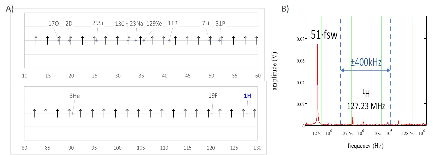
Figure 1: Frequency contents: A) Switching
frequency harmonics and nuclei
frequencies [MHz].
B) Zoom at proton frequency showing margin.
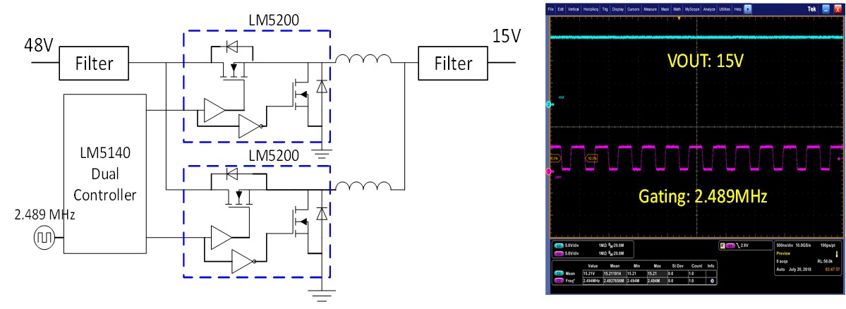
Figure 2: Circuit schematic and switching waveforms.
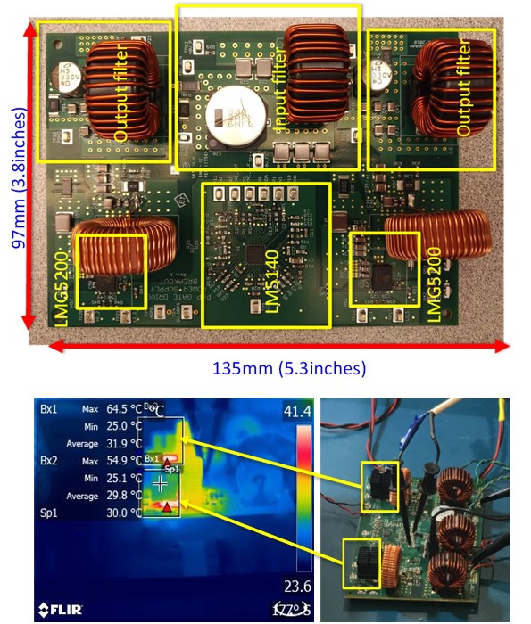
Figure 3: PS prototype and thermal tests.

Figure 4: Efficiency measurements.
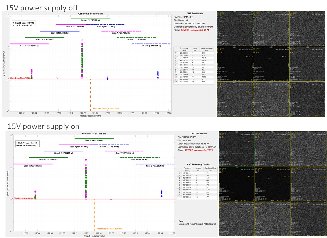
Figure 5: Coherent noise measurement
test. (Note: There is some noise detected in the room
not related to the power supply.)
DOI: https://doi.org/10.58530/2022/5047