5044
Mock TcMRgFUS Transducer for Off-site Technological Development1University of Utah, Salt Lake City, UT, United States
Synopsis
A portable device that mimics the shape, size, and configuration of the Insightec transcranial MR guided focused ultrasound (tcMRgFUS) assembly is presented. This Mock system provides a water bath and conductive ground plane that accurately emulates that of the Insightec system. The system is shown to generate the same well-known banding artifact as the Insightec system. The construction details of the Mock system and image comparison to the Insightec system are presented.
Introduction
The Insightec transcranial MRI guided focused ultrasound system (Insightec, Tirat Carmel, Israel) has become an important option in the treatment of essential tremor and other neurological disorders (1). This success has come in spite of noise and low signal banding artifacts associated with the large water volume and large conducting ground plane. Overcoming these artifacts and thereby improving patient safety and treatment efficacy will require the development of special purpose RF coils, support hardware, and pulse sequences that operate in conjunction with the Insightec system. Unfortunately, the Insightec system is typically installed in busy clinical areas, with very limited engineering access to the system. To enable engineering studies independent of the clinical system to develop improved RF coils and pulse sequences to address and overcome the system artifacts (2,3,4), we have developed and report on a portable, light weight device that mimics the Insightec transcranial transducer and can easily be used on multiple scanners and on the bench. This Mock system provides a water bath and conductive ground plane that are similar in shape, size, configuration and functionality to that of the Insightec system.Methods
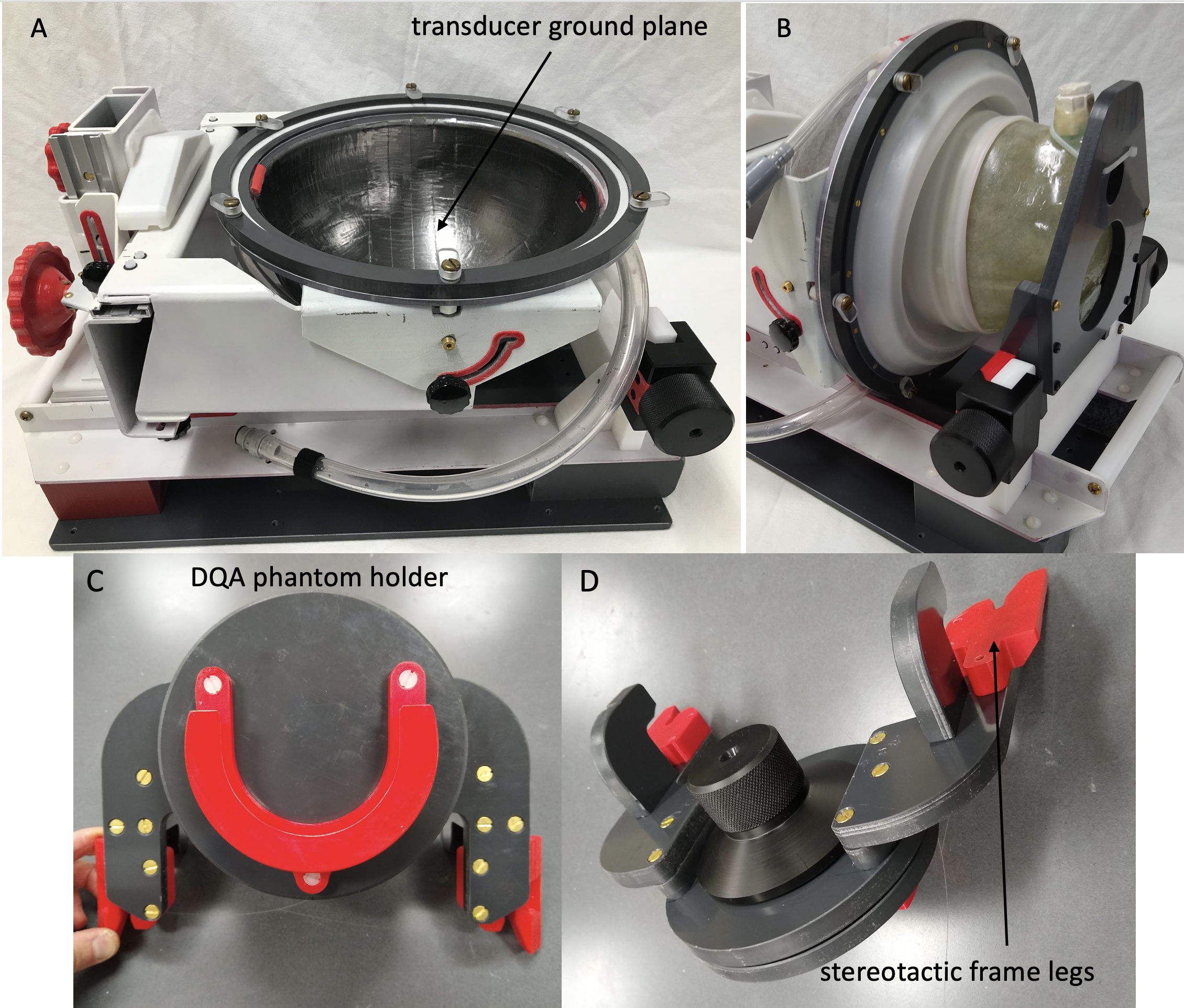
A 30 cm hemispherical polycarbonate former (California Quality Plastics, Inc.) was used to represent the Insightec Transcranial Transducer (ITT) surface. Graphite packing seal tape (McMaster-Carr) with adhesive backing, 2.54 cm wide, was attached on the inside surface of the former and adjacent edges were pressed together to create conductive connections across joints. This technique formed a solid, low conducting surface simulating the ITT surface contacting the water and ground plane (Figures 1 and 2).The open end of the Mock transducer was fitted with plastic rings, equivalent to the ITT membrane mounting structure. The Mock transducer was mounted on a fiberglass support structure that allows quick and easy rotation and positioning of the bowl at any angle from pre-clinical (Figure 2a) to clinical position (Figure 2b). The mounting device also allows for left-right, anterior-posterior, and superior-inferior translation along aluminum guide rails. For each direction of translation, a handwheel facilitates manual movement of the Mock transducer, and a locking knob fixes the assembly in the desired position during use (Figure 1B). The Mock support platform was designed so that the stereotactic frame mount and transducer bowl are in the same position on the scanner table as the ITT. The Data Quality Assurance (DQA) phantom holder of the ITT system was reproduced, fitting both the Mock and ITT systems. Additionally, a holder for a custom fiberglass head phantom was made to fit the stereotactic frame mount (example shown in Figures 1 and 2). The same membrane used during clinical treatments is used, and water is filled using a 1.3 cm diameter tubing and an electric or manual foot pump. Quickly draining water from the Mock system in clinical orientation is done using a gravity fed drain tube and opening the fill tube at the top of the bowl for vacuum relief. Non-proprietary detailed design information and parts list will be provided online upon acceptance of this abstract.
Imaging performance of the Mock transducer was evaluated with MRI experiments performed on a Siemens Skyra 3T MRI scanner (Siemens Healthineers, Erlangen, Germany). Imaging parameters are given in the results.
Results
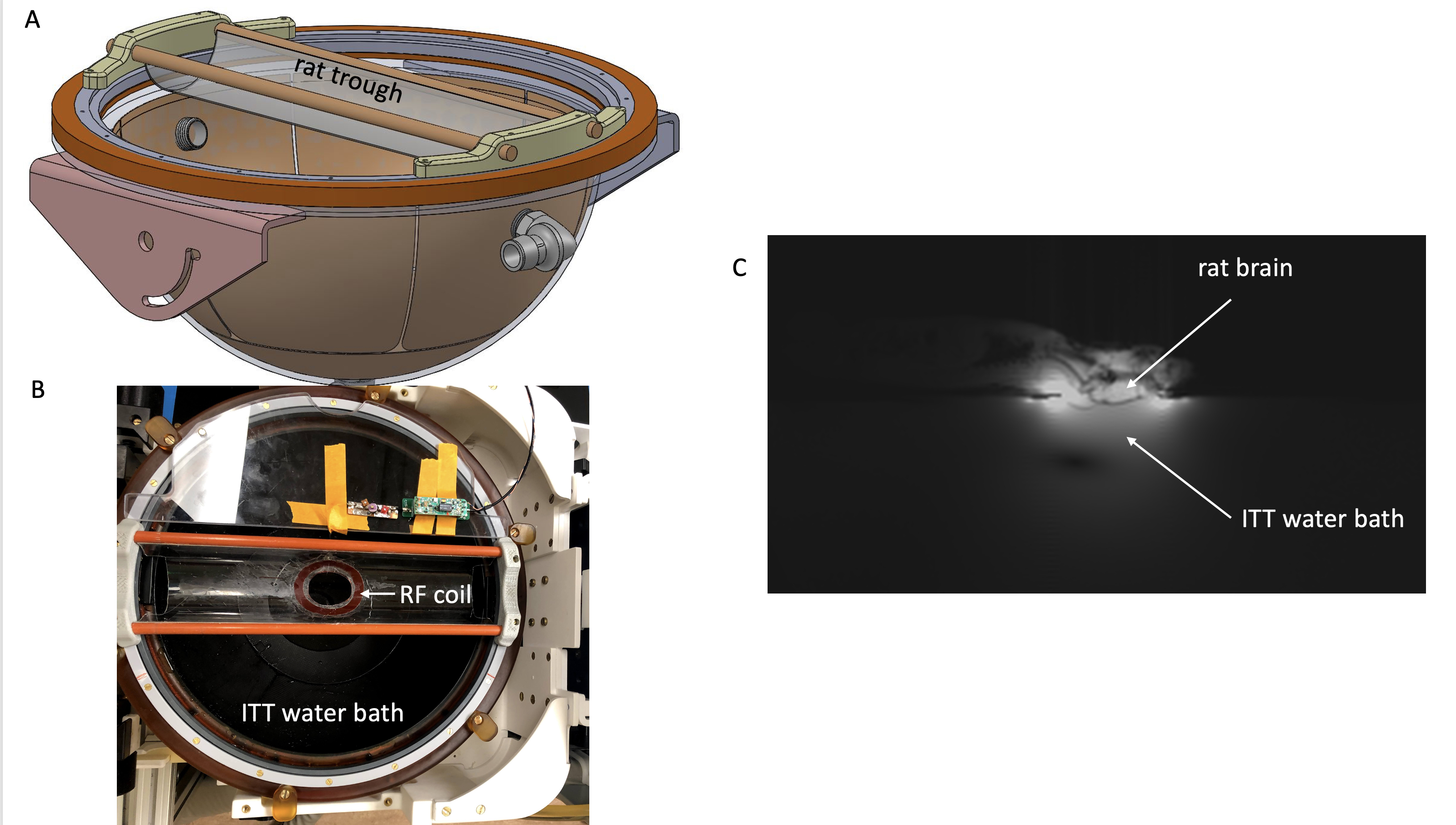
The Mock system demonstrated similar imaging characteristics to the ITT system such as increased B-field sensitivity towards the top of the dome and a low signal banding artifact near the open end of the dome. Examples of these artifacts can be seen in Figure 3.Using the Mock system, a rat holder and dedicated RF coil (Figure 4) were designed, tuned and matched without any access to the Insightec system, and tune and match were accurate when placed on the ITT system.
Discussion
The Mock system will greatly aid the development of specialized RF coils, imaging sequences and support hardware for both clinical and preclinical animal studies, reducing required ITT scan time.Results for the transcranial rat study demonstrated the ability to design the rodent support device with its accompanying RF coil on the lab bench using the Mock system. The coil, (very sensitive to water bath size and proximity) was tuned and matched on the Mock system and resulting tune and match on the clinical transducer was identical, dramatically reducing ITT experiment setup time. Pulse sequence development can be done using the Mock system, reducing clinical time even further.
Conclusions
We have developed a Mock transducer that simulates the ITT, with very similar imaging characteristics. The development of this transducer was relatively inexpensive. Its economic and convenience advantages have demonstrated great utility in streamlining the development and testing of experimental procedures on the ITT system. Tuning of preclinical RF coils and testing setups designed to interface with the ITT, can all be done offline such that clinical system setup is trivial and fast. Clinical system time is only required for experiments requiring ultrasound transmission.Acknowledgements
NIH grants: R01EB028316,_S10OD018482, S10S10OD026788References
1. Elias WJ, Lipsman N, Ondo WG, et al. A Randomized Trial of Focused Ultrasound Thalamotomy for Essential Tremor. N Engl J Med. 2016;375(8):730-9. doi: 10.1056/NEJMoa1600159. PubMed PMID: 27557301.
2. Yan X, Allen S, and Grissom WA. Propeller beanie passive antennas to alleviate dark bands in transcranial MR-guided focused ultrasound, ISMRM & SMRT Virtual Conference and Exhibition (2020), p113.
3. Hadley JR, Odeen H, Merrill R, Adams SI, Rieke V, Payne A, Parker DL. Improving image quality in transcranial magnetic resonance guided focused ultrasound using a conductive screen. Magn Reson Imaging 2021;83:41-49
4. Bitton RR, Sheingaouz E, Assif B, et al. Evaluation of an MRI receive head coil for use in transcranial MR guided focused ultrasound for functional neurosurgery, Int J Hyperthermia. 2021;38(1):22-29.
Figures