5043
Evaluation of a prototype MR conditional hoverboard and stirrups system for MR-guided brachytherapy at 3T1Radiation Oncology, Brigham and Women's Hospital, Dana-Farber Cancer Institute, Harvard Medical School, Boston, MA, United States, 2Diacor Inc, West Valley City, UT, United States
Synopsis
MR conditional stirrups would be beneficial in MR-guided gynecological and prostate brachytherapy but have not been clinically available. Evaluation of a prototype Diacor MR conditional board and stirrups system revealed no significant projectile or heating risks at 3T. The maximum temperature measured on its metallic surfaces after scanning was 22 ⁰C, relating to a 3 ⁰C increase. The stainless steel blades of the stirrup joints caused signal cancellation artifacts which extended radially up to 23cm on phantom images. On volunteer scans, artifacts were observed in posterior hip areas only. Pelvic organ visualization was considered suitable for brachytherapy treatment planning.
Introduction
MRI is increasingly employed for image guidance in gynecological and prostate brachytherapy in conjunction with CT, which is generally required for interstitial catheter reconstruction1. Differences in patient position between the two examinations can cause registration errors which may translate to radiation delivery errors. Recent advances in detecting brachytherapy applicators, seeds and needles on MR images2-4 present the opportunity to eliminate CT and consequently MR-CT misregistration. MR conditional stirrups would benefit the current MR-CT procedure by preserving patient position and would enable MR-only brachytherapy treatment planning workflows by allowing applicator or needle adjustments. To date, they have not been clinically available. This work evaluated a prototype MR conditional board and stirrups system for heating and artifacts during 3T MRI.Methods
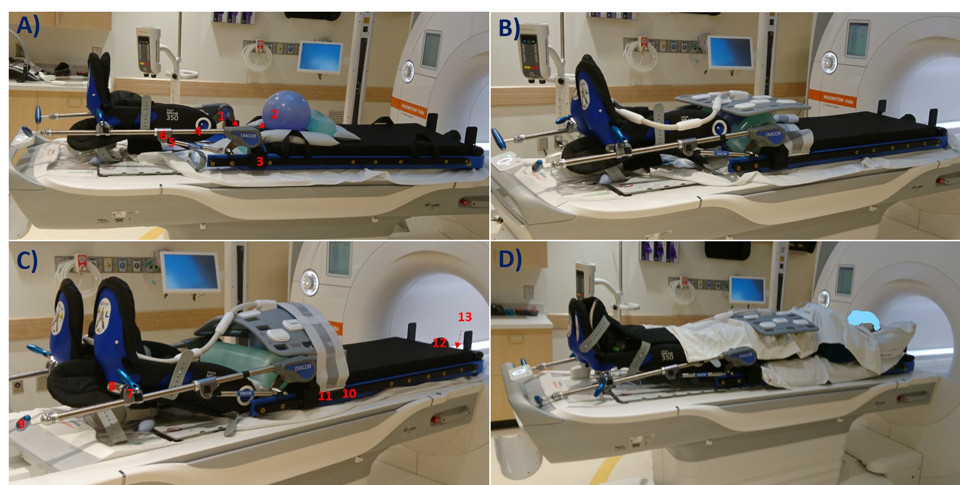
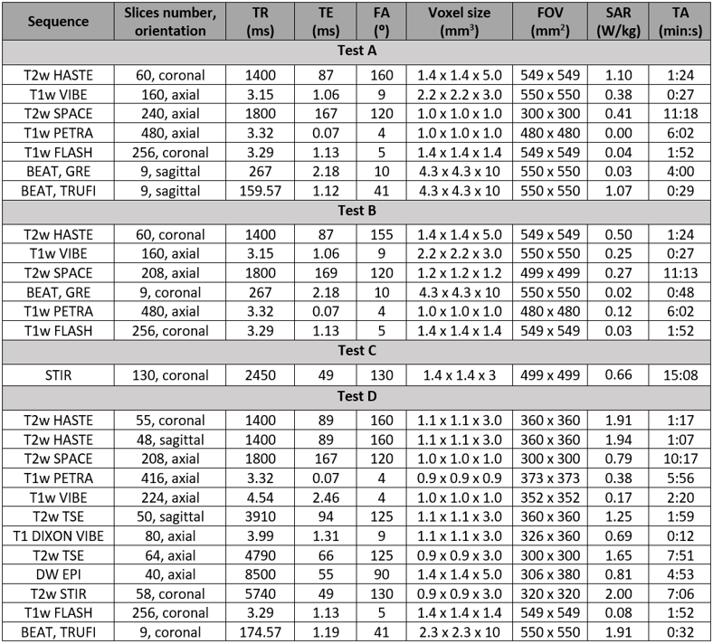
A prototype Diacor Zephyr HDR Hoverboard with MR-tek 350 stirrups was tested with a handheld magnet for attractive forces before being laid on a 3T Siemens Vida couch. Surface temperature was assessed at 13 locations along the device using a Fluke 62 Max non-contact infrared thermometer initially, and after each phantom test A-C (figure 1): A) A 24cm diameter spherical phantom on the hoverboard mat simulated the pelvis. One 1900ml cylindrical phantom was placed superiorly and one anteriorly to the sphere. B) The sphere flanked by both bottles covered the entire space between the stirrup joints, with the bottles touching the joints’ blades. C) The sphere was placed between the mat and a 5300ml cylindrical phantom. Clinical and research sequences with increased coverage (table 1) were acquired to determine the minimum artifact-free area in test A, and artifact extent in tests B-C. Ambient temperature was measured independently using the dedicated exam room thermometer at various timepoints throughout the study.D) Two consented healthy female volunteers were scanned on the hoverboard using brachytherapy protocols (table 1). MR images were evaluated for artifacts and pelvic organs visualization.
For all scans, receiving coils were: body 18 long (top), biomatrix spine 32 (bottom).
Results
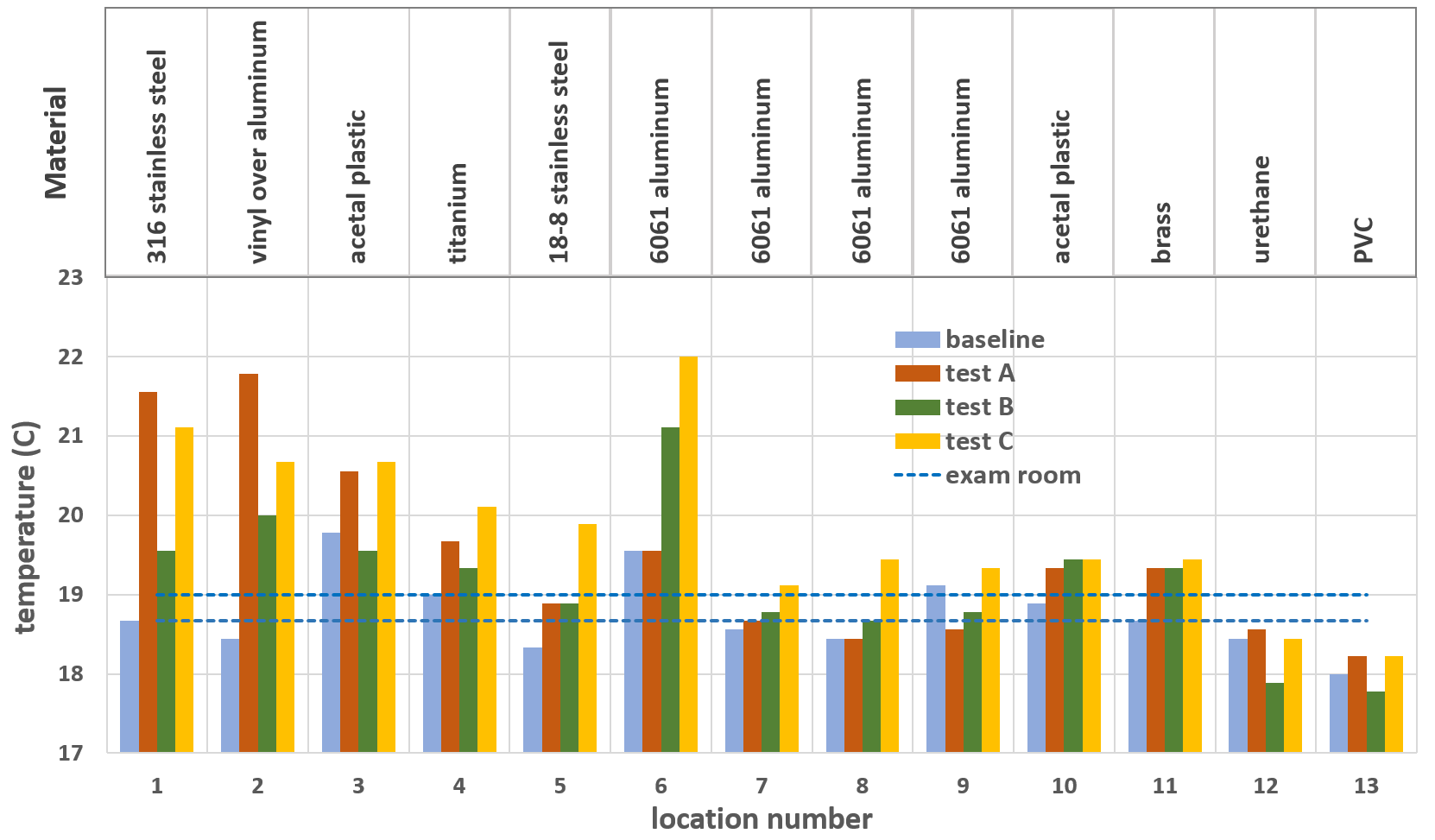
No parts of the assessed board and stirrups posed projectile risks at 3T. Temperature difference between phantom tests and baseline ranged from -0.6 ⁰C to 3.3 ⁰C (figure 2). The largest temperature increase of 3.3 ⁰C was observed after 27 minutes of MR acquisition for the vinyl covered aluminum joint of the stirrup (test A). The overall maximum measured temperature was 22 ⁰C for the aluminum gas spring rail mount after 15 minutes of continuous scanning, 3 ⁰C higher than the average room temperature (test C). Non-metallic parts of the hoverboard and stirrups, and those further from isocenter, demonstrated the least warming.The shortest observed artifact-free length on the spherical phantom was 18cm in superior-inferior direction for the VIBE and BEAT sequence with TRUFI contrast on test A, and 17cm in right-left direction on the VIBE images of test B. The maximum artifact extent measured from the stirrup blades was 18cm for the VIBE sequence of test B and 23cm on the test C STIR images (figure 3).
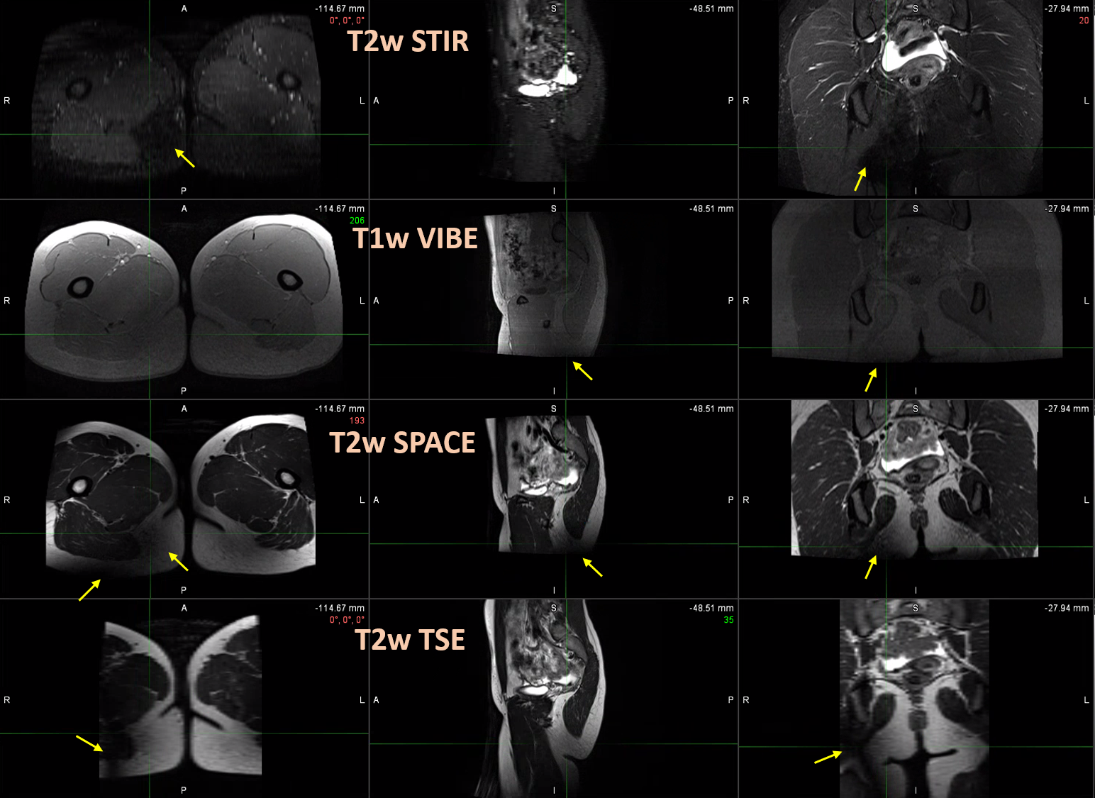
The board with mounted stirrups bearing volunteers fit well inside the 70cm bore MR scanner. The fully clothed volunteers reported feeling no warming at stirrup contact during the 45 minutes long examination. MR signal cancellation caused by the stirrups metallic plate was observed only on posterior hip areas and was most prominent on the T2-weighted STIR and TSE images (figure 4). A radiation oncologist deemed pelvic organ visibility adequate for treatment planning contour generation.
Discussion
Phantom tests revealed a maximum temperature increase of 3.3 ⁰C on the surface of metallic components of the board and stirrups after a total MR scan duration of 27 minutes. The highest measured temperature of 22 ⁰C was far below the lowest cutaneous thermal injury threshold of 44 ⁰C determined for exposure longer than 3 hours5. Therefore, the assessed device is not expected to pose thermal injury risks upon contact during or after 3T MRI.The wide variety of MR sequences used for the phantom and volunteer scans covers most clinical brachytherapy protocols. The employed phantoms provide uniform signal across their volume under ideal imaging conditions. Their placement aimed to represent a patient’s torso in test A, and to assess the entire space between the largest metallic stirrup components in tests B and C. Artifacts caused by the presence of metal were identifiable as characteristic dark areas on the phantom images. The main artifact sources were the stainless steel blades on the inner side of the stirrups, causing signal voids that extended up to 23cm radially on STIR images. Metal artifact measurements on phantoms may prove useful to inform protocol sequence selection and to optimize patient positioning on the hoverboard. Signal cancellation artifacts were also identified on volunteer scans, but they were confined in the posterior hip or leg area and did not affect genitourinary or gastrointestinal organ visualization. Thus, overall image quality was considered suitable for treatment planning purposes.
Conclusion
The evaluated Diacor Zephyr HDR Hoverboard and stirrups presented no MR safety risks at 3T. Although metal artifacts were observed closer to the stirrup joints on MR images, brachytherapy areas of interest in the pelvis remained unaffected. The device was considered suitable for clinical use in MR-guided brachytherapy.Acknowledgements
No acknowledgement found.References
1. Tharmalingam, H, Alonzi, R and Hoskin, PJ. The Role of Magnetic Resonance Imaging in Brachytherapy, Clinical Oncology 2018; 30(11):728–736.
2. Richart, J et al. Review of strategies for MRI based reconstruction of endocavitary and interstitial applicators in brachytherapy of cervical cancer. Reports of Practical Oncology and Radiotherapy 2018; 23(6):547–561.
3. Nosrati R, Paudel M, Ravi A, Pejovic-Milic A, Morton G, Stanisz GJ. Potential applications of the quantitative susceptibility mapping (QSM) in MR-guided radiation therapy. Phys Med Biol 2019; 64(14):ab2623.
4. Lee, C. Y. et al. Implementation of MRI-Only Treatment Planning (MRTP) for Gynecologic HDR Brachytherapy Using PETRA Sequence. Brachytherapy 2021; 20(3): S27–S28.
5. Moritz, AR, Herriques, FC Jr. Studies of thermal injuries: II The relative importance of time and surface temperature in the causation of cutaneous burns. Am J Pathol 1947; 23:695-720.
Figures