5035
Low-cost MR-compatible pneumatic respiratory motion simulator for development of MR-guided therapies1Radiology & Biomedical Imaging, University of California, San Francisco, San Francisco, CA, United States, 2Radiation Oncology, University of California, San Francisco, San Francisco, CA, United States
Synopsis
We developed a low-cost and simple MR-compatible respiratory motion simulator to support proof-of-concept studies of MR monitoring approaches with respiration-induced organ motion. The motion system integrates pneumatic control via an actuator subsystem outside the MRI and coupled via plastic tubing to a compressible bag for distention and retraction within the MRI motion subsystem and phantom within the MRI scanner. The proposed respiratory motion simulator provided consistent periodic respiratory motion with displacement in the range 3.7-9.0 mm. The respiratory simulator could be easily assembled with off-the shelf and 3D-printed parts, based on open-source design models.
Introduction
Abdominal organ motion causes significant errors in MR imaging when applied to MR-guided therapies of abdominal or pelvic organs due to organ shift and deformation.1–3 This necessitates a respiratory motion phantom to study for a new, motion-robust, and fast MR imaging in abdominal organs. A commercially available dynamic motion phantom has been used for the end-to-end verification of MRI-LINAC radiation therapy system.4,5 It is not a practical option for most acquisition technique development studies due to high cost. Several custom-made respiratory phantoms have been developed to evaluate motion compensation in MR imaging techniques.3,6,7 For new studies, the design and fabrication of a motion simulator from scratch may create a significant obstacle and increase the complexity of the project. Descriptions of motion simulator designs found in literature often lack the details, necessary to easily reproduce them. The goal of this study was to develop a low-cost, easy-to-make respiratory motion simulator to simulate respiration-induced abdominal organ motion inside the MRI bore.Methods
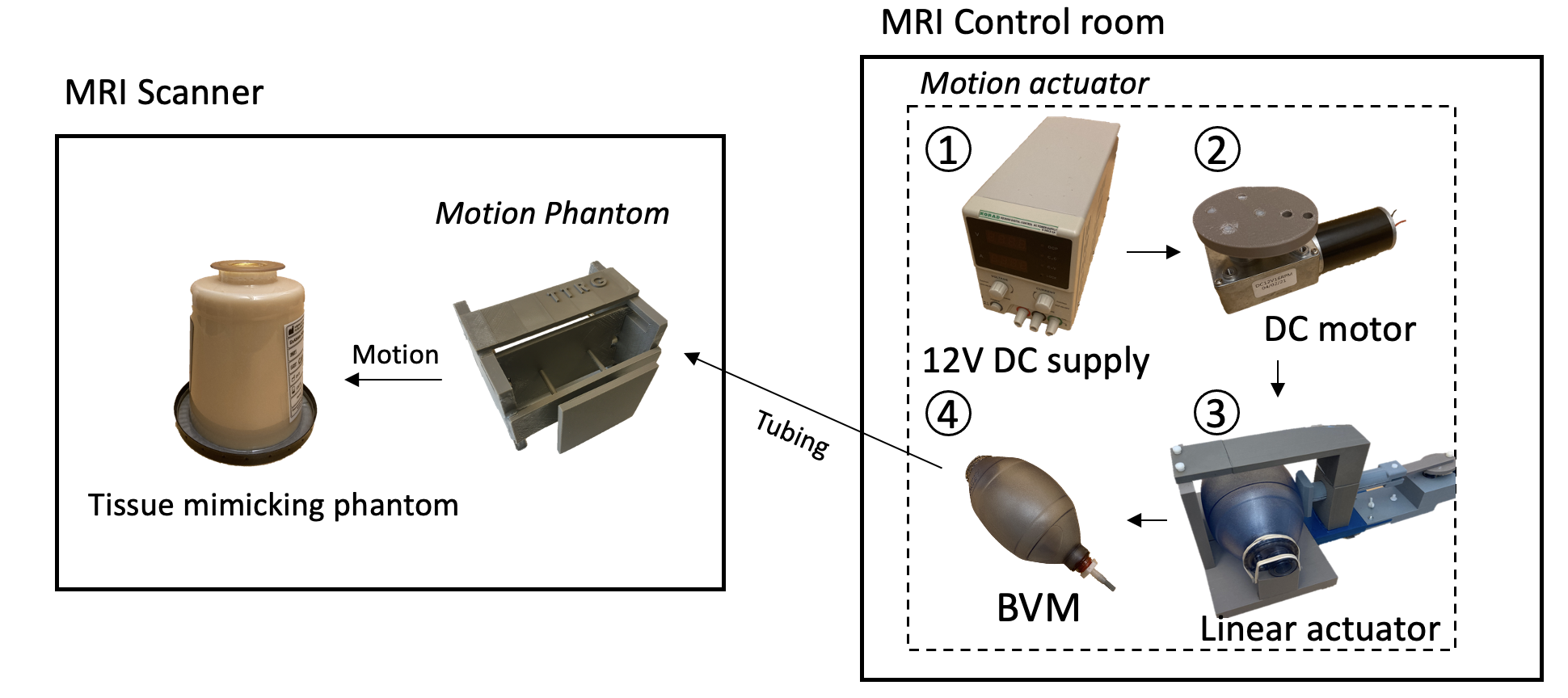
The respiratory motion simulator was designed based on the fabrication methods and components used in earlier approaches.3,6–8 In this study, we proposed a low-cost and simple fabrication process for the respiratory simulator. As shown in Fig.1, the respiratory motion simulator consists of two main parts: 1) Motion actuator located outside the MRI scanner; 2) Motion phantom placed inside the MRI scanner. The linear actuator creates a linear motion that can control the pressure inside the bag valve mask (BVM, volume: 1.8 L). The DC geared motor in the linear actuator featured a torque of 6.8649 Nm and a speed of 16 rpm, which was enough to control the BVM. The BVM is coupled via a flexible polymer tubing (Tygon) to the compressible bag in the motion phantom in the MRI scanner (Fig 1b). Elastic rubber bands in the motion phantom assembly provided the passive compression force necessary to cyclically pull the tissue-mimicking phantom back to the original position and re-inflating the BVM when not under compression. Finally, the motion phantom could be pneumatically controlled by the motion actuator and generate cyclical motion. The volume of the BVM was manually controlled by the plastic plate selection, which was placed between the BVM and the linear actuator. This volume control resulted in different amounts of displacement. In this study, the volumes of 1.65-1.8 L of the BVM were used to generate a various range of displacement. The completed simulator was evaluated using the accelerated MR imaging application on the RTHawk Research Platform (HeartVista, Menlo Park, CA).9 It featured an accelerated GRE sequence with a spiral readout trajectory to achieve real-time MR imaging. Respiratory motion was tracked with an integrated pencil-beam navigator sequence and quantified with a temporal window of 17 ms. MRI parameters included as follows: TR=25 ms, TE=14.8 ms, FOV= 280 280 mm, matrix=158, readout interleave=11. Navigators were set on the center of the phantom in a sagittal plane to track the movement. For the analysis, the magnitude images with the maximum and minimum displacement were converted to binary images and were subtracted to obtain the peak-to-peak distance. Finally, the normalized navigator positions were converted to the actual displacement using the resultant distance.Results
Figure 3 shows the time-dependent displacement of the phantom in the MRI scanner, with the 1.65 L volume of the BVM. The MR magnitude images indicate those at the maximum and minimum navigator positions in one of the respiratory cycles, respectively. Different thicknesses of the plate resulted in different moving distances of the phantom. The BVM and a preset of the plate allowed the tissue-mimicking phantom (1.2kg) to generate the stable amount of displacement in the range of 3.7-9 mm. The smaller volume of the BVM (higher compression) resulted in the larger displacement of the phantom.Discussion
In this study, we developed and evaluated a low-cost and simple MR-compatible respiratory motion simulator. It was built from off-the-shelf components and 3D-printed parts and did not require any programming. The simulator generated a periodic motion pattern, which simulated the motion of abdominal organs induced by respiration and flexible placement of the respiratory simulator was available in the MRI scanner. To increase or decrease a respiratory rate, the motor could be replaced with different speed motors, or could be used with the DC motor controller. All parts of the simulator were able to be easily 3D-printed from the open-source models and assembled by following the instructions, published on GitHub.10Conclusion
In this study, we presented a design for a low-cost MR-compatible respiratory motion simulator that can be easily replicated based on open-source 3D models and instructions. We have demonstrated its ability to generate controlled respiratory motion of a phantom weighing 1.2 kg with a maximum displacement of approximately 9 mm. This could lower the barriers to the development of new MR imaging techniques with motion compensation.Acknowledgements
This study was supported by National Institutes of Health (NIH) under Grants R21EB026018, R21CA230120, and R01EB025990.References
1. Vigen KK, Daniel BL, Pauly JM, Butts K. Triggered, navigated, multi-baseline method for proton resonance frequency temperature mapping with respiratory motion. Magn Reson Med. 2003;50(5):1003-1010. doi:https://doi.org/10.1002/mrm.10608
2. Chen GT, Jiang SB, Kung J, Doppke KP, Willett CG. Abdominal organ motion and deformation: implications for IMRT. Int J Radn Oncol Biol, Phys. 2001;51(3):210. doi:10.1016/S0360-3016(01)02209-X
3. Maier-Hein L, Pianka F, Müller SA, et al. Respiratory liver motion simulator for validating image-guided systems ex-vivo. Int J CARS. 2008;2(5):287-292. doi:10.1007/s11548-007-0140-2
4. Liu X, Li C, Zhu J, et al. Technical Note: End-to-end verification of an MR-Linac using a dynamic motion phantom. Med Phys. 2021;48(9):5479-5489. doi:10.1002/mp.15057
5. Fatemi-Ardekani A, Wronski M, Kim A, Stanisz G, Sarfehnia A, Keller B. SU-E-J-209: Geometric Distortion at 3T in a Commercial 4D MRI-Compatible Phantom. Med Phys. 2015;42(6Part10):3313-3313. doi:10.1118/1.4924295
6. Bour P, Ozenne V, Marquet F, Senneville BD de, Dumont E, Quesson B. Real-time 3D ultrasound based motion tracking for the treatment of mobile organs with MR-guided high-intensity focused ultrasound. Int J Hyperthermia. 2018;34(8):1225-1235. doi:10.1080/02656736.2018.1433879
7. Han F, Zhou Z, Cao M, Yang Y, Sheng K, Hu P. Respiratory motion-resolved, self-gated 4D-MRI using rotating cartesian k-space (ROCK). Med Phys. 2017;44(4):1359-1368. doi:10.1002/mp.12139
8. Black DG, Yazdi YO, Wong J, et al. Design of an anthropomorphic PET phantom with elastic lungs and respiration modeling. Med Phys. 2021;48(8):4205-4217. doi:10.1002/mp.14998
9. Ozhinsky E, Salgaonkar VA, Diederich CJ, Rieke V. MR thermometry-guided ultrasound hyperthermia of user-defined regions using the ExAblate prostate ablation array. J Ther Ultrasound. 2018;6. doi:10.1186/s40349-018-0115-5
10. Kim K. Respiratory Motion Simulator. Thermal Therapy Research Group, University of California, San Francisco; 2021. https://github.com/mri-kisoo/RespiMotionSimulator
Figures