5034
Modular, 3D Printed, Open-source Phantoms for Small Animal Systems
Mariko Gardiner1, Anthony G. Tessier2, Keith Wachowicz2,3, and Nicola De Zanche2,3
1University of Alberta, Edmonton, AB, Canada, 2Medical Physics, Cross Cancer Institute, Edmonton, AB, Canada, 3Oncology, University of Alberta, Edmonton, AB, Canada
1University of Alberta, Edmonton, AB, Canada, 2Medical Physics, Cross Cancer Institute, Edmonton, AB, Canada, 3Oncology, University of Alberta, Edmonton, AB, Canada
Synopsis
Phantoms for pre-clinical systems have not been standardized, and none in the literature permit the wide variety of measurements possible with the ACR phantoms. We present a low-cost, open-source, modular phantom made of 3D-printed and off-the-shelf parts that mimics the functionality of the ACR phantoms on an appropriate scale. Standard, inexpensive manufacturing techniques are sufficient to create the fine features required at this scale. Configuration of the phantom can be customized to suit each site’s needs. Possible measurements include image uniformity, distortion and SNR; slice location, thickness, and angle; radial, linear, and low-contrast resolution.Introduction
While quality assurance (QA) phantoms for clinical applications have been standardized by ACR1 and NEMA2, sites with pre-clinical, animal MR scanners typically develop ad-hoc procedures and phantoms for QA. Those that have been described in the literature3-5 have limited capabilities compared to the clinical phantoms. For example, none have features to assess high and low contrast resolution, slice position, slice thickness and slice orientation. Manufacturing such phantoms on an appropriate scale is also more challenging than those made for human MR systems. We present a modular phantom that uses 3D printed, milled, and off-the-shelf parts to overcome these limitations.Methods
The phantom consists of a standard 7.8 mM CuSO4 and 61.6 mM NaCl aqueous solution6 within a 50 mL centrifuge tube (inner diameter approximately 26 mm tapering down to 25 mm at the base), in which several 25 mm diameter modules are stacked to provide the following features.a) Slice location: two sets of intersecting ramps angled at 90° to each other (tilted 45° from the axis in opposite directions).
b) Slice thickness: two sets of parallel planes tilted 10° from the transverse plane to define a thin slab from which the slice profile is measured2.
c) Slice angle: crossed triangular prisms to detect slice tilt (in which case the arms of the resulting cross in the image are not parallel).
d) Radial resolution7: 36 radially-oriented spokes (5° wedges) taper down to 50 μm.
e) Linear resolution: two sets of rectangular slots ranging from 0.5 mm to 50 μm in width.
f) Low-contrast resolution: holes of different sizes in disks thinner than the slices acquired.
g) Distortion grid: rectangular grid of holes in a material at least as thick as the slices acquired.
h) Spacer: annulus or ring of uniform thickness maintains adjacent modules parallel and provides a region of uniform signal for measurements such as image uniformity and SNR.
All modules are designed with multiple points of contact to the adjacent modules to maintain parallel alignment. To facilitate filling, modules d and e include 4 semicircular passages at the periphery. Care must be taken to ensure that air bubbles are not trapped in the fine features of the modules or between modules. FreeCAD8 drawings of the modules can be scaled to match the dimensions of other containers as needed.
Modules a-e were 3D printed using stereolithography because its resolution and fidelity (nominally 50 μm for our supplier) are superior to those of the more common fused deposition modelling process. Modules f and g were milled using an LPKF ProtoMat S62 out of 0.8 mm FR4 (0.5 mm ⌀ holes, 1 mm pitch) and thin (0.1 and 0.35 mm) plastic sheets, respectively (Fig.3). Module f was also made from a standard perforated prototyping printed circuit board (without copper pads or traces) resulting in a coarser (2.54 mm pitch) grid.
The spacer (h) is used to separate modules and to provide regions of uniform signal. In this implementation the spacers were standard R17 rubber o-rings, but they can also be off-the-shelf nonmetallic washers, 3D printed or machined using standard techniques.
Images of the phantom were acquired on a 9.4T scanner (Magnex 21.5 cm horizontal bore magnet and 120 mm ⌀ gradient bore (Magnex Scientific, Oxford, UK), NRC TMX Spectrometer (National Research Council of Canada Institute for Biodiagnostics West, Calgary, Canada)) using a 38 mm ID birdcage mouse coil (Doty Scientific DSI-1441) and a multislice spin echo sequence (~90° tip angle, slice thickness = 0.5 mm, 30 axial slices, resolution 256⨉256, FOV = 30⨉30 mm2, TR = 1850 ms, TE = 18 ms, 1 average).
Results and Discussion
Three-dimensional CAD drawings of the modules in FreeCAD8 format are available for download (https://github.com/dezanche/preclinical_MRI_phantom). Stacked view and renderings of the individual modules are shown in Fig. 1 and Fig. 2, respectively. Photographs of the milled low-contrast resolution and distortion grid modules are shown in Fig. 3, and the remaining modules are shown in Fig. 4. A photograph of the complete assembled phantom is shown in Fig. 5.The acquired MR images are in the bottom rows of Fig. 2. Some manufacturing imperfections are present in modules d and e (arrows) because the feature sizes are at the limit of the stereolithography process (50 μm). Some susceptibility artefacts are visible in the low-contrast resolution disk, likely caused by a susceptibility mismatch between the liquid and plastic. The effects of air inclusions are also present in the low-contrast resolution and slice thickness disks.
Conclusion
We have developed the first open-source, modular, scalable phantom platform that allows quantitative animal scanner performance assessment in terms of various common parameters. The phantom has functionality similar to that of the ACR phantom, with the addition of being customizable to a site’s individual needs. Although some imperfections are present, standard, inexpensive manufacturing techniques are sufficient to create the features required at this scale. Cost of the phantom as built is approximately $50 (US).Acknowledgements
We acknowledge funding from the Natural Sciences and Engineering Research Council (Canada) and a student stipend from the University of Alberta. We thank Dr. Adam Maunder for fabricating modules f and g, and Dr. Ashwin Iyer’s electromagnetics research group for access to the ProtoMat machine.References
- Large and Medium Phantom Test Guidance for the ACR MRI Accreditation Program. American College of Radiology, 2021. https://www.acraccreditation.org/-/media/ACRAccreditation/Documents/MRI/ACR-Large--Med-Phantom-GuidanceFinal.pdf
- National Electrical Manufacturers Association, “Determination of Slice Thickness in Diagnostic Magnetic Resonance Imaging,” National Electrical Manufacturers Association, Rosslyn, Virginia, NEMA MS 5-2018, 2018.
- E. Yoshimaru, J. Totenhagen, G. E. Alexander, and T. P. Trouard, “Design, manufacture, and analysis of customized phantoms for enhanced quality control in small animal MRI systems: Customized Phantoms for Small Animal MRI Systems,” Magn. Reson. Med., vol. 71, no. 2, pp. 880–884, Feb. 2014, doi: 10.1002/mrm.24678.
- J. O’Callaghan et al., “Is Your System Calibrated? MRI Gradient System Calibration for Pre-Clinical, High-Resolution Imaging,” PLoS ONE, vol. 9, no. 5, p. e96568, May 2014, doi: 10.1371/journal.pone.0096568.
- B. L. Cox, K. D. Ludwig, E. B. Adamson, K. W. Eliceiri, and S. B. Fain, “An open source, 3D printed preclinical MRI phantom for repeated measures of contrast agents and reference standards,” Biomed. Phys. Eng. Express, vol. 4, no. 2, p. 027005, Jan. 2018, doi: 10.1088/2057-1976/aa9491.
- E. Jackson et al., “Acceptance Testing and Quality Assurance Procedures for Magnetic Resonance Imaging Facilities,” American Association of Physicists in Medicine, AAPM Report No. 100, Dec. 2010. doi: 10.37206/101.
- A. A. Heikal, K. Wachowicz, and B. G. Fallone, “MTF behavior of compressed sensing MR spectroscopic imaging,” Med. Phys., vol. 40, no. 5, p. 052302, Apr. 2013, doi: 10.1118/1.4800642.
- Juergen Riegel, Werner Mayer, Yorik van Havre. FreeCAD (Version 0.19). http://www.freecadweb.org
Figures

Figure 1: Exploded view of a possible stacking arrangement of modules (respectively, a, c, e, g, d, b, f, f, and f) and spacers (h, multiple positions).
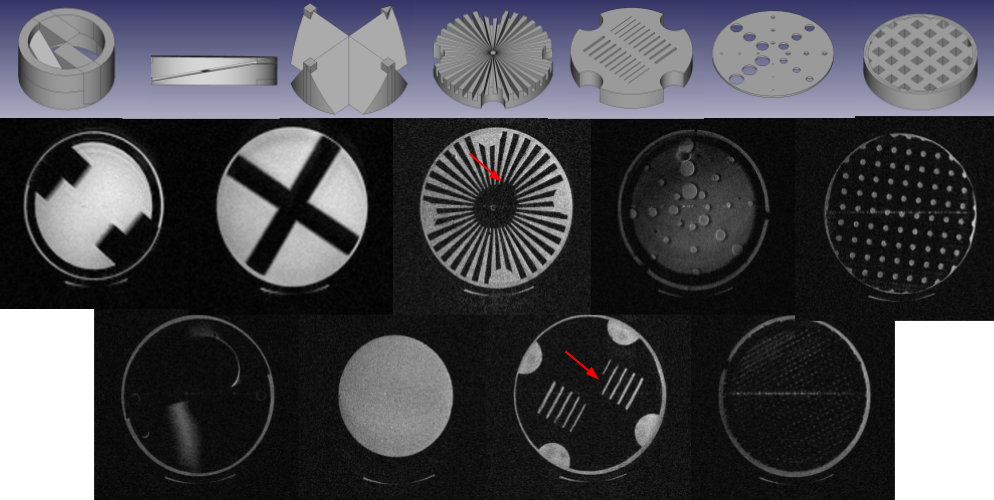
Figure 2: Renderings of phantom modules a-g (top row), and corresponding images (including coarse and fine distortion grids (d) and uniform region (h)).
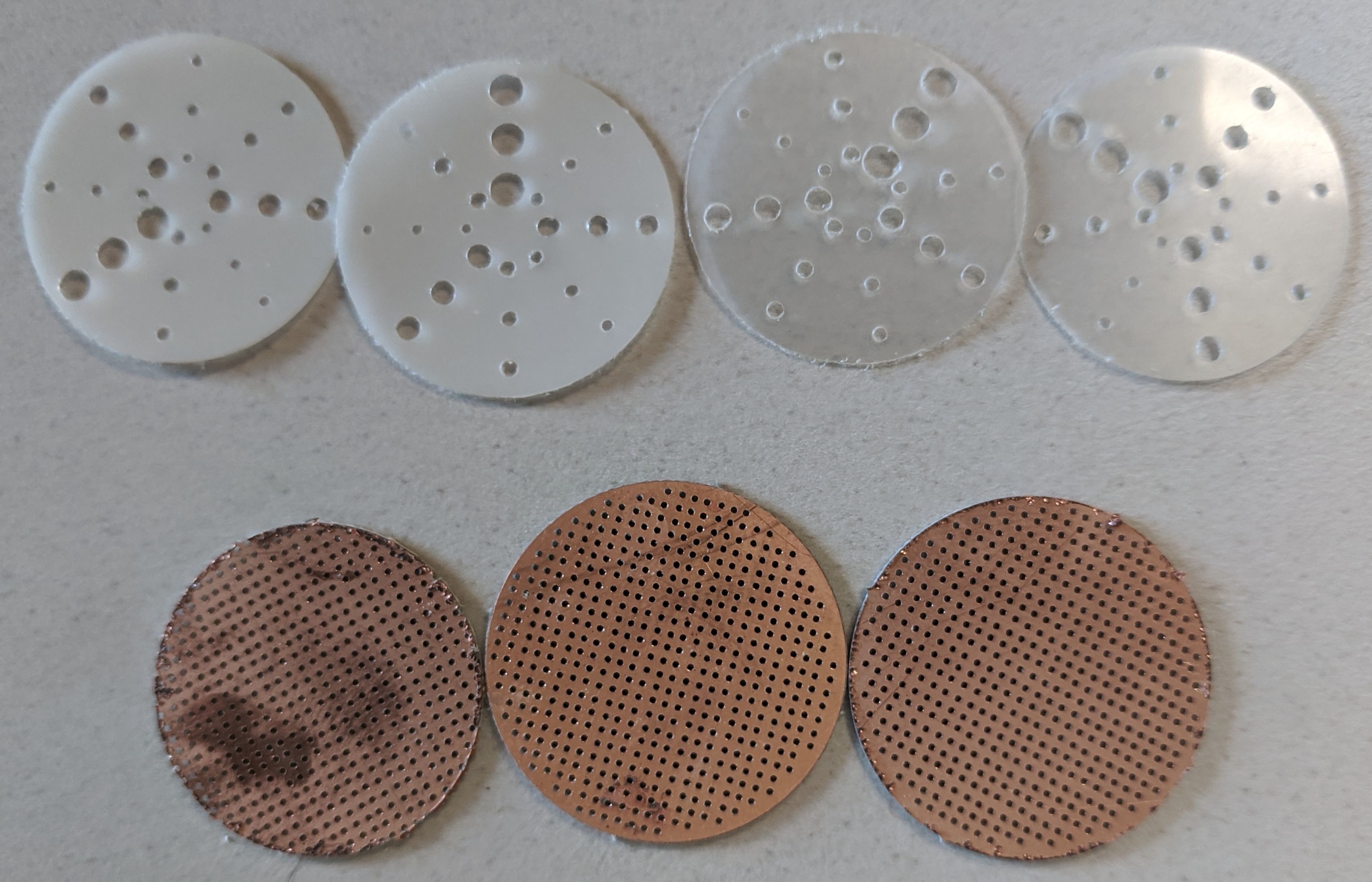
Figure 3: Low-contrast resolution (top) and 1-mm pitch distortion grid (bottom) inserts fabricated using PCB milling equipment. Materials are thin plastic sheet (top) and 0.8 mm FR4 (bottom).
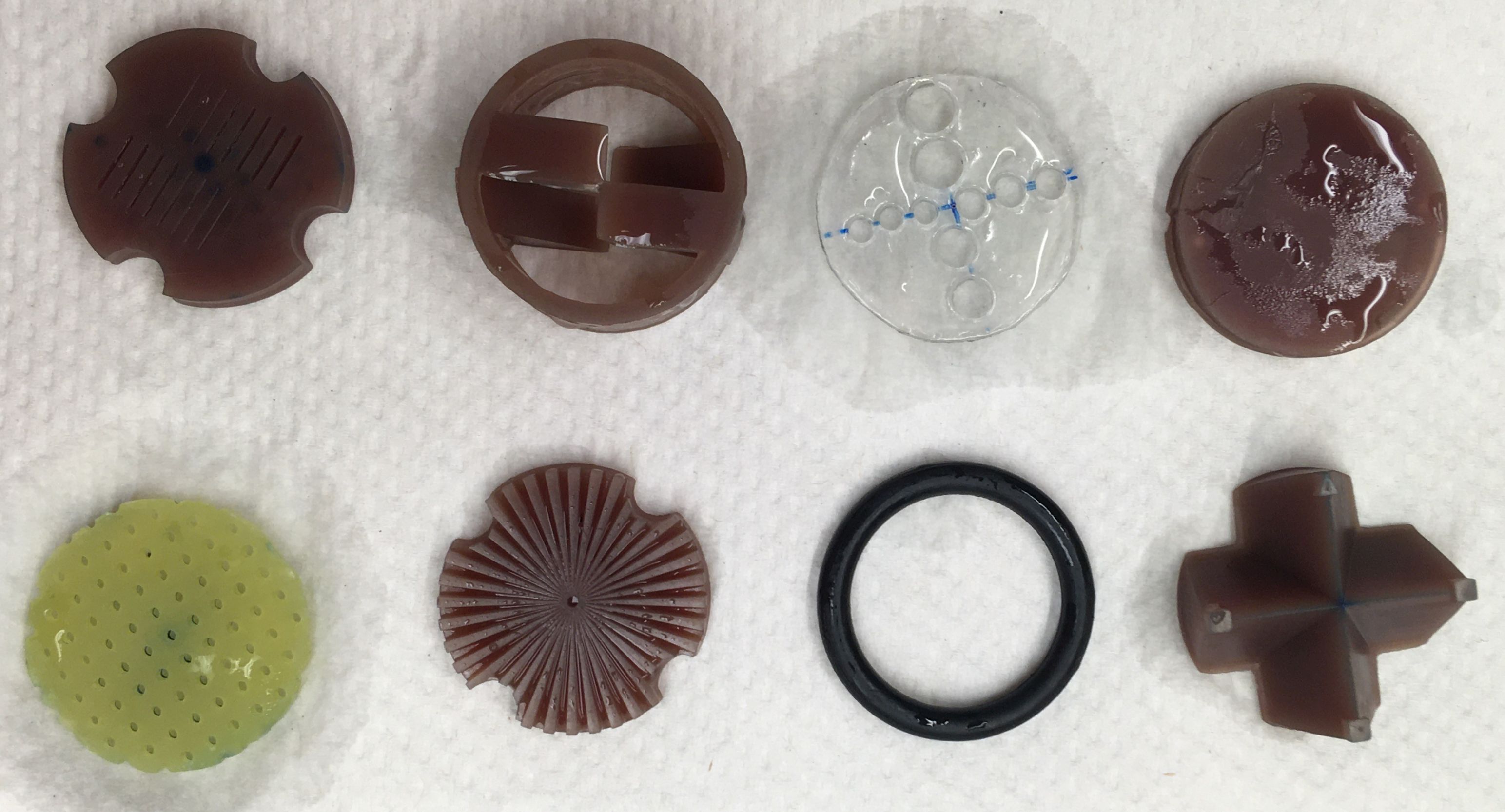
Figure 4: Fabricated phantom modules (left to right, top to bottom): e, a, f (not used), b, g, d, h, and c. Materials are stereolithography resin (brown modules), 1.6 mm FR4 (2.54-mm pitch distortion grid), and rubber (o-ring).
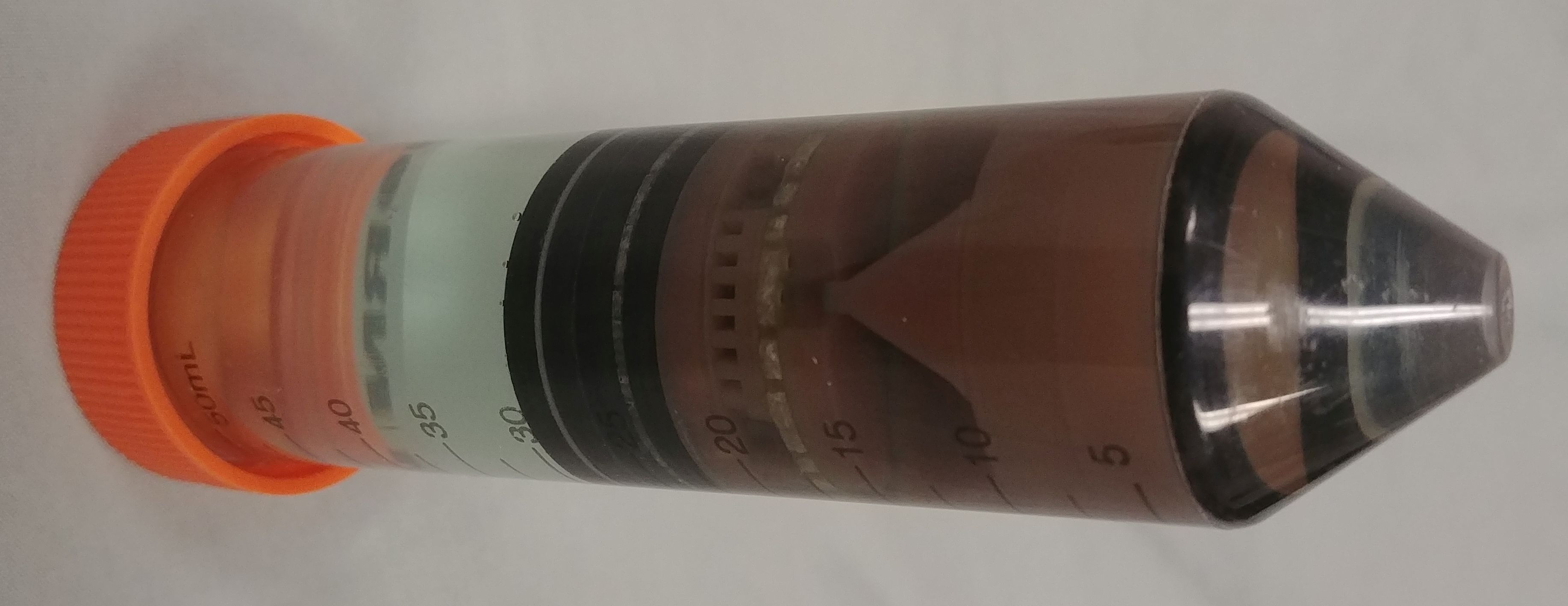
Figure 5: Photograph of the assembled phantom used to acquire images. From left to right, modules are h, f, h, f, h, f, h, b, d, g, e, c, a, and h. The container is a 50 mL centrifuge tube.
DOI: https://doi.org/10.58530/2022/5034