5032
Distortion Measurements Using a Large-volume, Lightweight, Modular MRI Phantom With Solid Signal Sources
Mariko Gardiner1, Keith Wachowicz2,3, and Nicola De Zanche2,3
1University of Alberta, Edmonton, AB, Canada, 2Oncology, University of Alberta, Edmonton, AB, Canada, 3Medical Physics, Cross Cancer Institute, Edmonton, AB, Canada
1University of Alberta, Edmonton, AB, Canada, 2Oncology, University of Alberta, Edmonton, AB, Canada, 3Medical Physics, Cross Cancer Institute, Edmonton, AB, Canada
Synopsis
Phantoms that cover large volumes are required to characterize geometrical distortion for image-guided interventions such as MR-guided radiation therapy (linac-MR). Liquid-filled phantoms of appropriate size can, however, be impractically heavy. Our phantom uses silicone rubber spheres arranged on a three-dimensional grid, resulting in a lightweight, portable structure. Displacements of each bead relative to the known grid positions are calculated in Matlab or 3D Slicer from 3D bSSFP scans. Design files and image processing code are available online.Introduction
Image-guided interventions, such as MR-guided radiation therapy (linac-MR1), require periodic assessment of image distortion for quality assurance. For such applications, distortion must be measured over a volume at least as large as the body part being treated, which is usually in the trunk region. Consequently, a measurement is needed over most of the scanner’s useful FOV, which can be a 40 cm DSV (33.5 L) or larger. Existing phantom designs (e.g., the ACR phantoms2) consist mostly of containers filled with a liquid such as water or oil. When scaled up to the required dimensions, the mass of the phantom can easily exceed what are considered in many jurisdictions to be safe lifting weights (e.g., the common 23 kg limit under optimal conditions3). Heavy, liquid-filled phantoms are also impractical and fragile because of the stresses placed on the container material, leading to a significant risk of a large leak or spill.Proprietary phantoms that employ small markers have been reported4 but are not widely available. Soft supplement capsules (e.g., vitamins, oils) can be used as markers, but they are not spherical in shape and they are also chemically and dimensionally unstable in the long term. Hydrogel markers are also impractical because they must be kept moist to compensate for evaporation.
The objective of this work was to develop a practical, large-volume distortion phantom that can be readily handled by a single person (e.g., <10kg).
Methods
The phantom was designed using off-the-shelf parts as much as possible. The proton signal is generated by silicone rubber beads (9 mm ⌀ spheres with a 2 mm ⌀ axial hole for mounting), attached to a support structure using M2 nylon screws and nuts. The support structure consists of stacked polypropylene sheets, 3.3 mm thick and with 4 mm ⌀ holes at regular intervals (standard 25.4 mm “peg board”). The sheets are joined using nylon threaded rods and separated by stand-offs 22.1 mm in height, resulting in a 3-dimensional grid with isotropic pitch. Slotted side panels can be added to increase flexural, torsional, and shear stiffness. The present configuration uses 11 sheets with 11⨉18 holes, for a possible 2178 sample locations with a mass of 5.7 kg without side panels. Three rows from the edges of the boards were populated with 1386 beads, covering a volume of 28 L (density ~0.2 kg/L). More positions can be populated if desired, but may not be necessary because distortion is greatest at the periphery. A 25 mm ⌀ container filled with ~12 mL of petroleum jelly is placed at the centre of the phantom for automatic flip angle and frequency calibration.The phantom (Fig. 1) was scanned in a 3T Philips Achieva with high-linearity gradients (model TNF2) and distortion correction disabled, using a 3D bSSFP sequence with the following parameters: 1.25 ms echo time, 420⨉280⨉280 mm3 FOV, 1⨉1⨉1 mm3 voxels, 25° flip angle, 2 averages (6:50 minutes total scan duration). Echo times less than approximately 2 ms must be used because the signal from the beads’ silicone decays rapidly. The body coil was used for excitation and signal reception.
Data was saved in DICOM format and processed offline as follows using a Matlab script or interactively in 3D Slicer5 (https://www.slicer.org/) (with Python scripts executed within Slicer’s command-line interface):
- Segment by thresholding to identify beads and reject noise
- Ignore regions with less than 200 contiguous voxels to reject artefacts and signal from incomplete beads
- Calculate centroid of each bead
- Align beads to known grid using rigid transformations
- Calculate distance between each bead and nearest grid position
Results and Discussion
Three-dimensional CAD drawings of the phantom (Fig. 2) are available for download (https://github.com/dezanche/MRI_distortion_phantom) in FreeCAD6 format, along with the scripts used for analysis.The beads provide ample signal to identify their shape and centroids except at the edges of the acquisition volume where some are not entirely visible because of B0 inhomogeneity (in this scan 1228/1386 beads are identified). The phantom succeeds in measuring distortion out to the edges of the scanner’s field of view with sufficient signal and without the excessive weight of flood-field phantoms.
Positions and displacements are displayed in 3D, and 2D scatter plots of different components of the displacement can also be generated (Figs. 3 and 4).
A detailed bill of materials of the phantom as built is provided in Fig. 5, for which the total cost was less than $200 (US).
Conclusion
The modular phantom described here fills an important gap and allows measurement of geometrical distortion over large volumes without the excessive mass of liquid-filled phantoms. Its modular design is inexpensive and can be adapted to a wide range of scanners and applications (e.g., staircased layers to fit the curved inner volume of a cylindrical scanner). The solid samples function well at 3T (and likely at higher B0 fields), provide ample signal and will not deteriorate over time (decades of estimated minimum useful life).Future work includes building larger versions of the phantom contoured to the scanner bore, and fitting the measured distortion to analytical models.
Acknowledgements
We acknowledge funding from the Natural Sciences and Engineering Research Council (Canada) and a student stipend from the University of Alberta. We thank Philips Healthcare for technical support, and Curtis Osinchuk and Lance Spiridon for assistance with construction of the phantom.References
- S. Chin et al., “Magnetic resonance‐guided radiation therapy: A review,” J Med Imaging Radiat Oncol, vol. 64, no. 1, pp. 163–177, Feb. 2020, doi: 10.1111/1754-9485.12968.
- Large and Medium Phantom Test Guidance for the ACR MRI Accreditation Program. American College of Radiology, 2021. https://www.acraccreditation.org/-/media/ACRAccreditation/Documents/MRI/ACR-Large--Med-Phantom-GuidanceFinal.pdf
- T. R. Waters, V. Putz-Anderson, A. Garg, and L. J. Fine, “Revised NIOSH equation for the design and evaluation of manual lifting tasks,” Ergonomics, vol. 36, no. 7, pp. 749–776, Jul. 1993, doi: 10.1080/00140139308967940.
- D. A. Roberts et al., “Machine QA for the Elekta Unity system: A Report from the Elekta MR‐linac consortium,” Med. Phys., vol. 48, no. 5, pp. e67–e85, May 2021, doi: 10.1002/mp.14764.
- R. Kikinis, S. D. Pieper, and K. G. Vosburgh, “3D Slicer: A Platform for Subject-Specific Image Analysis, Visualization, and Clinical Support,” in Intraoperative Imaging and Image-Guided Therapy, F. A. Jolesz, Ed. New York, NY: Springer New York, 2014, pp. 277–289. doi: 10.1007/978-1-4614-7657-3_19.
- Juergen Riegel, Werner Mayer, Yorik van Havre. FreeCAD (Version 0.19). http://www.freecadweb.org
Figures

Figure 1: Left: Photograph of distortion phantom. Right: phantom setup for scanning.

Figure 2: Left: 3D rendering of phantom with side panels removed. Right: detail of bead and fastening system consisting of (bottom to top) M2 ⨉ 16 mm nylon screw, nylon spacer/reducer (2mm ID to match the screw, 4 mm OD and flange to match pegboard holes), silicone bead, and M2 nylon nut.
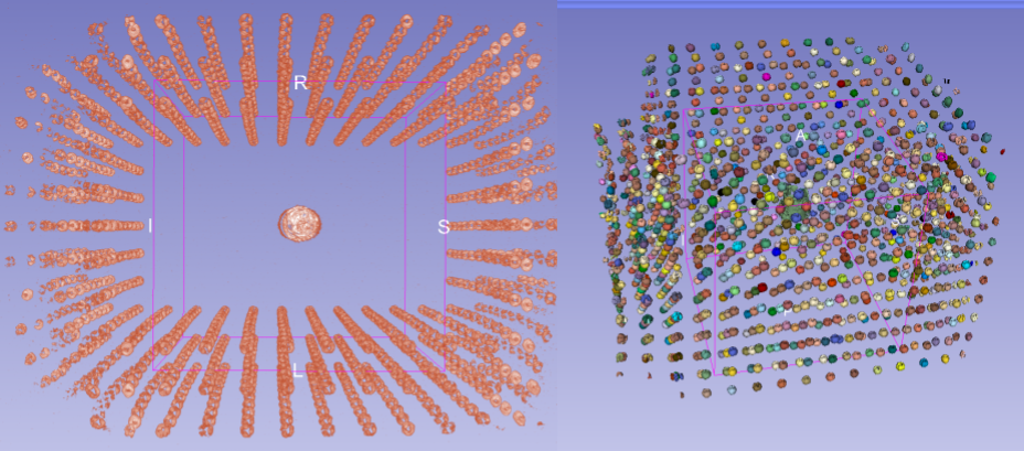
Figure 3: Visualizations of acquired data. Left: 3D rendering (MIP, top view). Right: after segmentation.
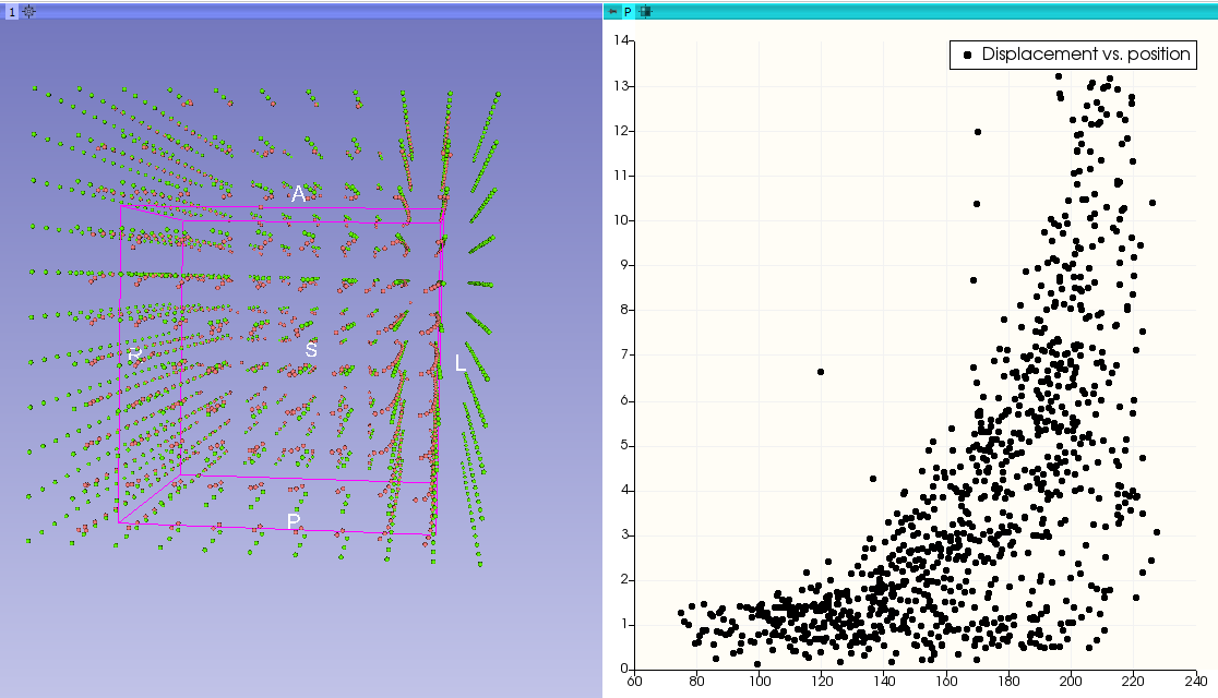
Figure 4: Left: 3D rendering of measured centroids of the beads (red) and grid positions (green). Right: scatter plot of each bead’s displacement as a function of its radial position relative to isocentre (both in mm).
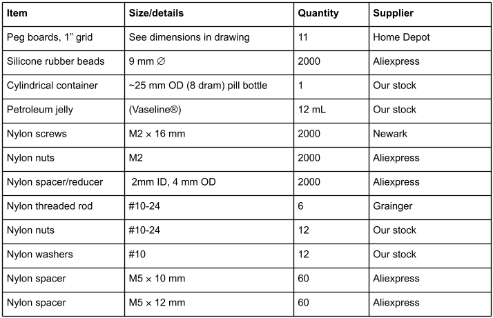
Figure 5: Bill of materials used to construct the modular distortion phantom.
DOI: https://doi.org/10.58530/2022/5032