5031
Mobile application based monitoring system for RF coils at 7T Magnetic Resonance Imaging1Arizona State University, Tempe, AZ, United States, 2Barrow-ASU Center for Preclinical Imaging, Phoenix, AZ, United States
Synopsis
Like most modern electronic devices, a mobile application based Radio Frequency (RF) coil monitoring system will make it easy to carry out any real-time changes to the RF coil. This work focuses on developing a mobile application based RF monitoring system, that allows the user to gather real-time RF coil characteristics and control the coil. It gives the user a chance to make changes when necessary. The opportunity to wirelessly implement such changes without physical contact with the coil, using a mobile application via Bluetooth is a step in the direction towards building next-generation RF coils for MRI.
Introduction
With MR scanners becoming increasingly complex, most of the scanners have a built-in and proprietary monitoring system for Radio Frequency (RF) coils and interface circuits. These integrated RF monitoring systems have very little options to incorporate an RF coil built in-house. Here arises a need for a mobile application based, open source RF monitoring system that does not disturb the transmit (Tx) and receive (Rx) chain of the MR scanner. Previous studies have delved slightly into developing a real time RF monitoring system but none of them were close enough to a standalone wireless module. This study involves design and development of a stand-alone, wireless RF monitoring system that presents features like wireless impedance control to tune and match, forward and reflected RF power measurement, and decoupling among coil elements along with much potential for future applications.Method
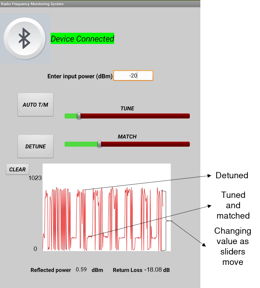
An L-matching network with single series and shunt capacitors (trimmer) was designed along with MEMS (ADGM1304, Analog Devices, USA) switch and 8 capacitors (0505 series Non-magnetic, PassivePlus, USA) with fixed capacitances to create a capacitor bank as shown in Fig.1(Bottom). This matching network board can generate a combined of 255 states for tuning and matching. A directional coupler is used to couple a portion of the reflected power using a logarithmic power detector (AD8307, Analog Devices, USA) and fed to a microcontroller (Espressif Systems, CHINA) which also controls the MEMS switches. On the user end, an Android application using the MIT App inventor has been developed, to control the RF monitoring system as shown in Fig.2. After pairing the module to the application via Classic Bluetooth connection, user has the option to enter the input power in dBm. This allows the user to get a glimpse of the return loss in real-time as they change the capacitance values. The mobile application allows the user to control the impedance with the help of two sliders to change the capacitance value of the tuning and matching capacitors and an AUTO T/M button to carry out a fully automatic impedance matching function. While changing the slider bar, reflected power from the power detector will be displayed on the canvas as a plot ranging from 0-1023. The lowest number will correspond to tuned and matched state for the RF coil.Results and Discussion
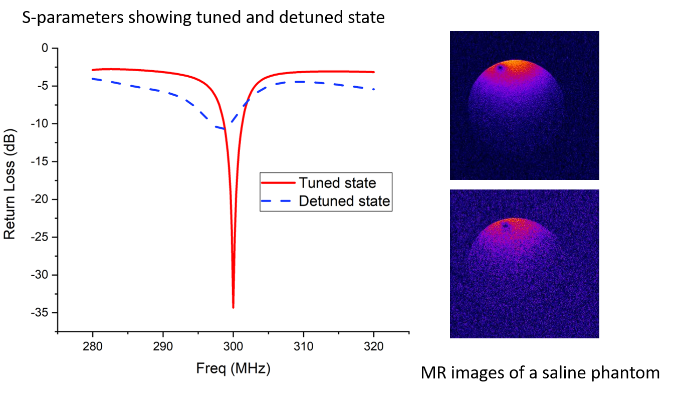
A surface coil made out of copper wire and a two-port VNA (FieldFox N9923A, Keysight Technologies, USA) is used to gather the S-parameters and validate the performance of the system on the test bench. Fig.3(Left) shows the tuned and detuned conditions of the coil while using the Android application to control the MEMS switches. All the MR imaging studies were conducted at Barrow Neurological Institute - Arizona State University (BNI-ASU), Center for Preclinical Imaging, using a 7T small-animal, 30-cm horizontal-bore magnet and BioSpec Avance III spectrometer (Bruker, Billerica, MA) with a 116-mm high-power gradient set (600 mT/m). Fast-Low-Angle-Shot (FLASH) Sequence with a repetition time (TR) of 350 ms, echo time (TE) of 5.4 ms, and a flip angle (α) of 40 degrees was used for MR imaging experiments. A field of view (FOV) of 40 x 40 mm and 256 x 256 matrix leading to an in-plane resolution of 156 x 156 µm, in addition 9 slices were acquired along the sample with a slice thickness of 1 mm. A saline solution filled in a 50 mL centrifuge tube is used as a phantom to replicate small animals. Same slices (8/9) of the MR images for both tuned and detuned condition were selected to compare the image quality.Conclusion
This work shows the feasibility for a general purpose RF monitoring module that includes wireless impedance control and the ability to detune (Rx coils only) . The mobile application also gives us the opportunity to view real time reflected power plot. This feature is helpful when MRI consoles do not possess the ability to plot return loss. This prototype will be further developed to a multichannel, high power capable module which will assist in building a stand-alone and open source RF monitoring system for MRI scanners.Acknowledgements
This work was supported by the National Institute Of Biomedical Imaging And Bioengineering of the National Institutes of Health under Award Number R00EB020058.References
1. Sohn, S. M., DelaBarre, L., Gopinath, A., & Vaughan, J. T. (2015). Design of an Electrically Automated RF Transceiver Head Coil in MRI. IEEE transactions on biomedical circuits and systems, 9(5), 725–732. https://doi.org/10.1109/TBCAS.2014.2360383
2. El-Sharkawy, A. M. M., Qian, D., Bottomley, P. A., & Edelstein, W. A. (2012). A multichannel, real-time MRI RF power monitor for independent SAR determination. Medical Physics, 39(5), 2334–2341. https://doi.org/10.1118/1.3700169
Figures