5030
A Truncated Twisted Solenoid RF Phase Gradient Transmit Coil for TRASE MRI1University of Alberta, Edmonton, AB, Canada
Synopsis
TRASE is an MR imaging sequence that achieves k-space encoding through the use of phase gradients in the RF transmit field. The twisted solenoid is the most efficient RF transmit coil used for TRASE encoding; however, the geometry results in a long coil with a relatively short imaging volume. We introduce a new truncated design for the twisted solenoid to increase the usable imaging volume relative to the coil’s size. Simulation studies conducted indicate the truncated design can create similar imaging volumes to the untruncated version whilst significantly reducing the coils length by as much as a half.
Introduction
TRASE is an MR imaging technique that performs k-space encoding through the use of RF transmit phase gradients, rather than gradients of the main magnetic field. The replacement of B0 gradients by RF transmit phase gradients allows alternative low-cost MRI systems to be constructed from small permanent magnets, such as a Halbach array1.The twisted solenoid has been previously demonstrated as a promising coil for TRASE imaging2. High one-dimensional spatial resolutions have been achieved with the twisted solenoid in phantom studies2,3; however, this specific coil geometry creates large gaps at the end of the RF transmit coils due to the protruding twisted turns (See Fig. 1a). The gaps created by the twisted turns lead to a decreased B1 magnitude uniformity towards the end of the coils, requiring the twisted solenoid to be significantly longer relative to its usable imaging volume. In this study we modified the coils by truncation to better fit coil conductors upon a cylindrical former of limited length, while maintaining or improving imaging performance.
Methods
The design process of the truncated twisted solenoid was as follows: (1) the axial truncation distance is specified (2) for the first coil turn, any portion of the turn beyond the truncation distance is flattened (3) each successive turn with a portion beyond the truncation point is then flattened a fix distance below the previously flattened turn. A truncated twisted solenoid compared to an untruncated twisted solenoid are shown in Fig. 1.The truncated twisted solenoid can be described by the following geometric parameters: coil turn radius, coil length, modulation amplitude, pitch, and number of turns. Coil optimization was performed by first selecting the coils diameter and length based on the desired target imaging volume and physical constraints. Optimization was performed through a parameter search using Biot‐Savart simulations with the BSMag MATLAB package. As required by the TRASE sequence, the B1 magnitude inhomogeneity was restricted to ±10% and a mean B1 phase gradient strength greater than 5.0 deg/cm over the target imaging volume2,4. Coils were primarily optimized for B1 magnitude uniformity.
Results
For a target imaging volume 100mm in length and 80mm in diameter, two truncated twisted solenoids were constructed, a 125mm diameter 15-turn outer coil and a 100mm diameter 16-turn inner coil. Before truncation, the length of the outer coil and inner coils were 320mm and 290mm respectively; both coils were truncated to a length of 200mm. Coils were wound with 20 AWG wire around a 3D printed PLA cylindrical former. The coil pair was geometrically decoupled using a short 30mm long 6-turn clockwise and 5-turn counterclockwise regular solenoid added to the end of the outer and inner truncated twisted solenoids respectively (See Fig. 2)3. The geometric parameters, mean phase gradient strength, and mean B1 magnitude for the inner and outer coils from the optimization simulation results are given in Fig. 3. Within the 100mm target imaging volume length, the optimized coils had a B1 magnitude uniformity better than ±10% at 80% the coils diameter, as shown in Fig. 4.The one-dimensional TRASE sequence was performed on a Halbach array with a central resonant frequency of 2.836 MHz1. The coil pair and a cylindrical bottle phantom of diameter 35mm and length 40mm containing a molar concentration of 61.6 mM NaCl and 7.8 mM CuSO4 was centered within the magnet. The sequence consisted of a 200 µs hard pulse for both excitation and refocusing, an echo spacing of 2000 µs, repetition time of 2000ms, an echo train length of 128, and 16 averages. The obtained one-dimensional TRASE profile is shown in Fig. 5. The width of the 1D phantom profile was roughly 30 pixels. For the 35mm diameter phantom this corresponds to a mean pixel size of 1.16mm/pixel and a mean B1 phase gradient of Gx = 12.1 deg/cm. In tandem, the truncated coil pair have a simulated effective field gradient strength of Gx = 11.0 deg/cm and expected mean pixel size of 1.28mm/pixel.
Discussion
Simulations indicate the truncated design, while significantly shorter, maintains a similar imaging volume and spatial resolution (i.e. phase gradient strength) to the untruncated twisted solenoid. The truncated coil set presented here boasted a high level of B1 magnitude uniformity. The 200mm long nested coil pair allowed an imaging volume 100mm in length and 80mm in diameter. This coil pair is roughly half the length of previously published untruncated twisted solenoid pairs whilst obtaining a slightly larger target imaging volume3.The experimental one-dimensional TRASE image resembles the expected peaked excited volume caused by the Halbach arrays B0 pattern (Fig. 5)1. The phase gradient strength determined from the pixel size is slightly greater than expected, but within an acceptable level of uncertainty.
Conclusion
Based on the simulation studies conducted, this new truncated twisted solenoid design is significantly shorter than the predecessor untruncated version whilst maintaining similar imaging quality. This truncated coil will allow practical imaging volumes to be obtained for a more compact TRASE RF transmit coil. Experimental results indicate that TRASE using the truncated twisted solenoid can be performed on small portable Halbach array, which could lead to the development of a low-cost, accessible MR imaging system.Acknowledgements
No acknowledgement found.References
1. A. R. Purchase et al., "A Short and Light, Sparse Dipolar Halbach Magnet for MRI," in IEEE Access, vol. 9, pp. 95294-95303, 2021
2. Sun H, Yong S, Sharp JC. The twisted solenoid RF phase gradient transmit coil for TRASE imaging. J Magn Reson. 2019; 299:135–150.
3. Sun H, AlZubaidi A, Purchase A, Sharp JC. A geometrically decoupled, twisted solenoid single-axis gradient coil set for TRASE. Magn Reson Med 2019; 83:1484–98.
4. Sharp JC, King SB, Deng Q, Volotovskyy V, Tomanek B. High‐resolution MRI encoding using radiofrequency phase gradients. NMR Biomed. 2013; 26:1602–1607.
Figures
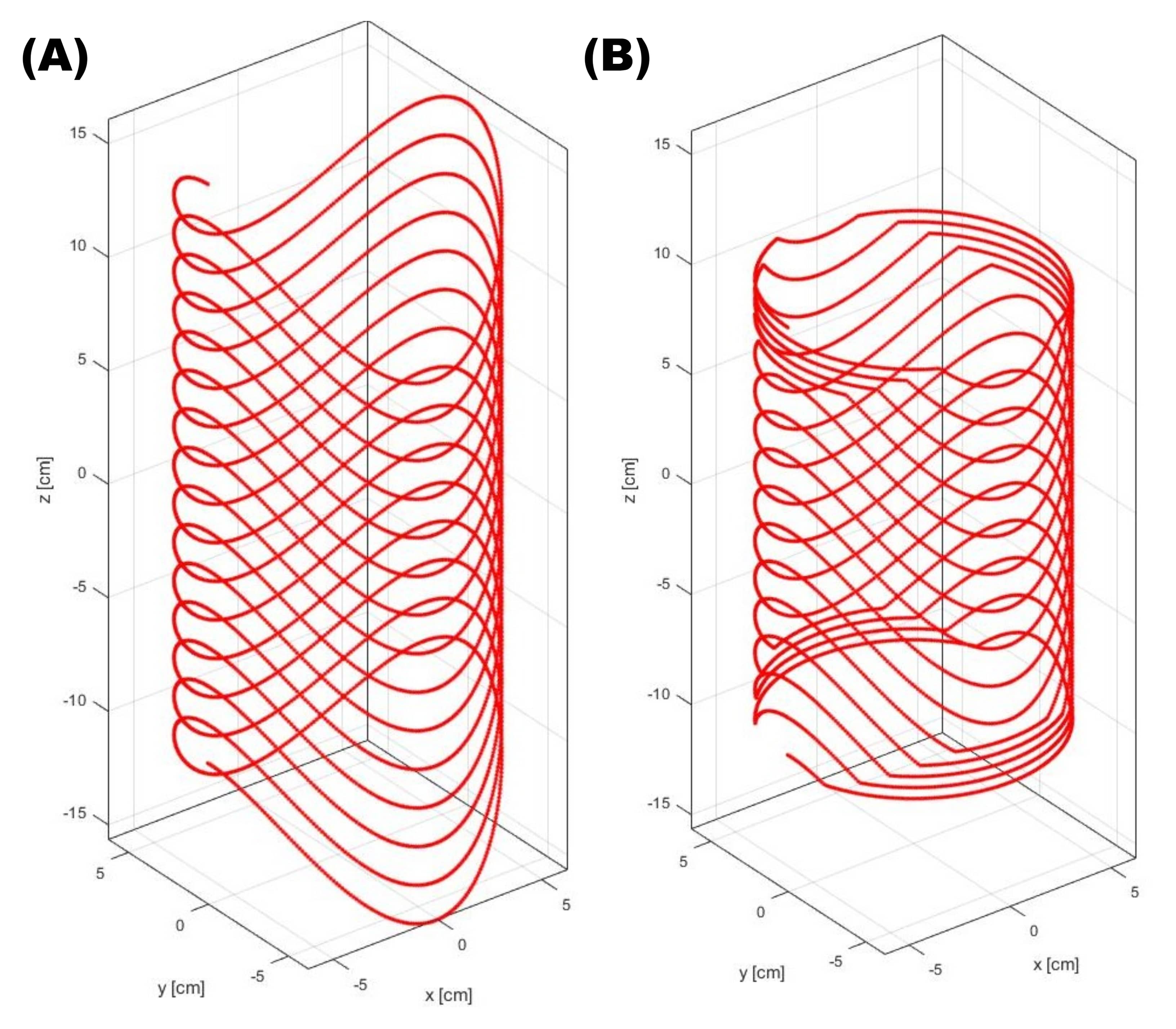
Figure 1: Three-dimensional view of the coil geometry for the (A) twisted solenoid and (B) truncated twisted solenoid

Figure 4: A display of the nested concentric truncated twisted solenoids. The coils are rotated 90o relative to each other to produce a opposite gradients along the same transverse axis. The coils were geometrically decoupled by regular solenoids added to both coils with opposite revolutions. The
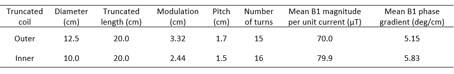
Figure 2: Optimal coil geometries for the outer and inner truncated twisted solenoids. Coils were optimized to maximize the B1 magnitude uniformity within the imaging volume.
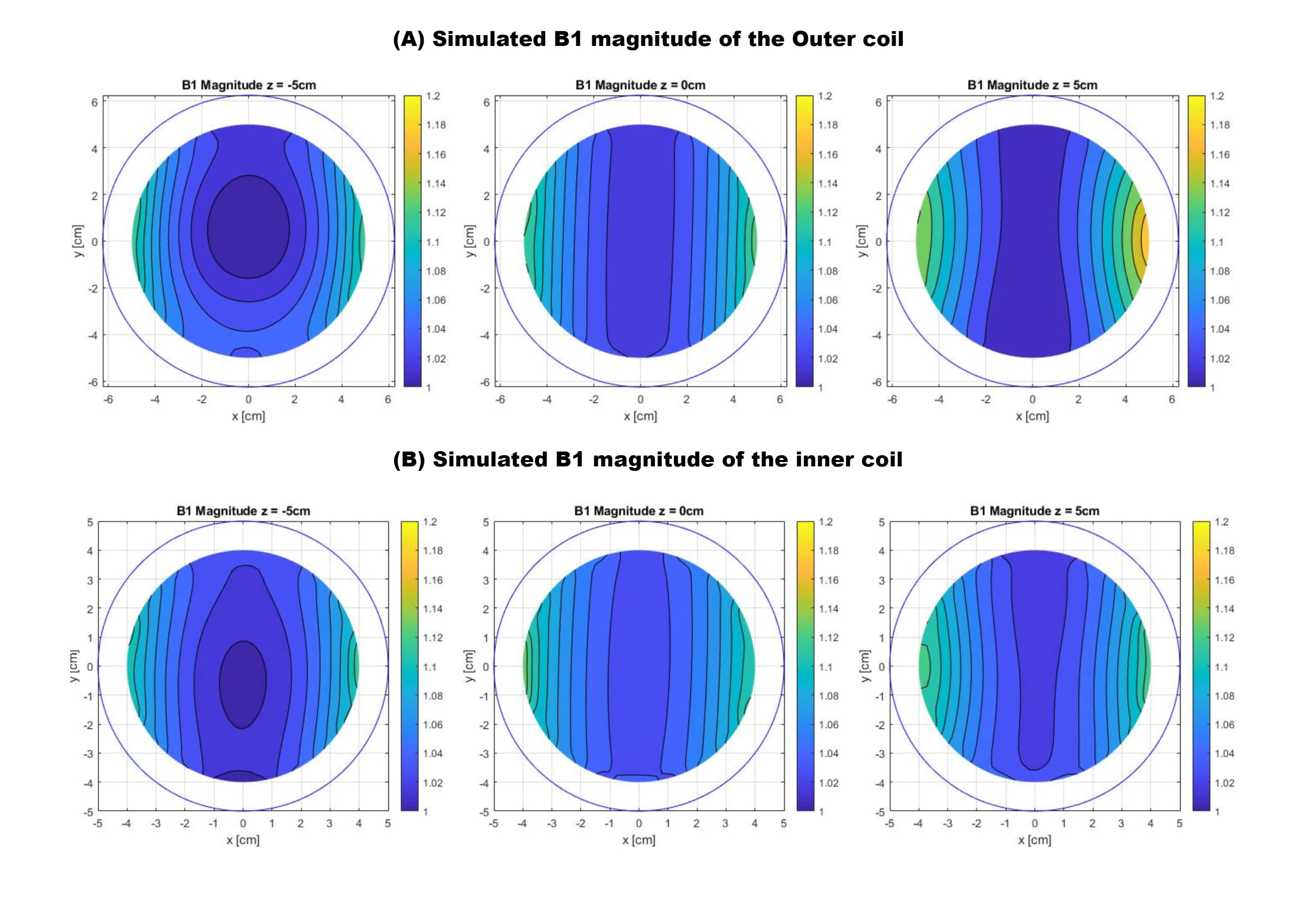
Figure 3: Biot-Savart simulation of the normalized B1 magnitude maps of the (A) Outer and (B) Inner coils at three planes within the 10cm long imaging volume (z = -5cm, 0cm, 5cm).
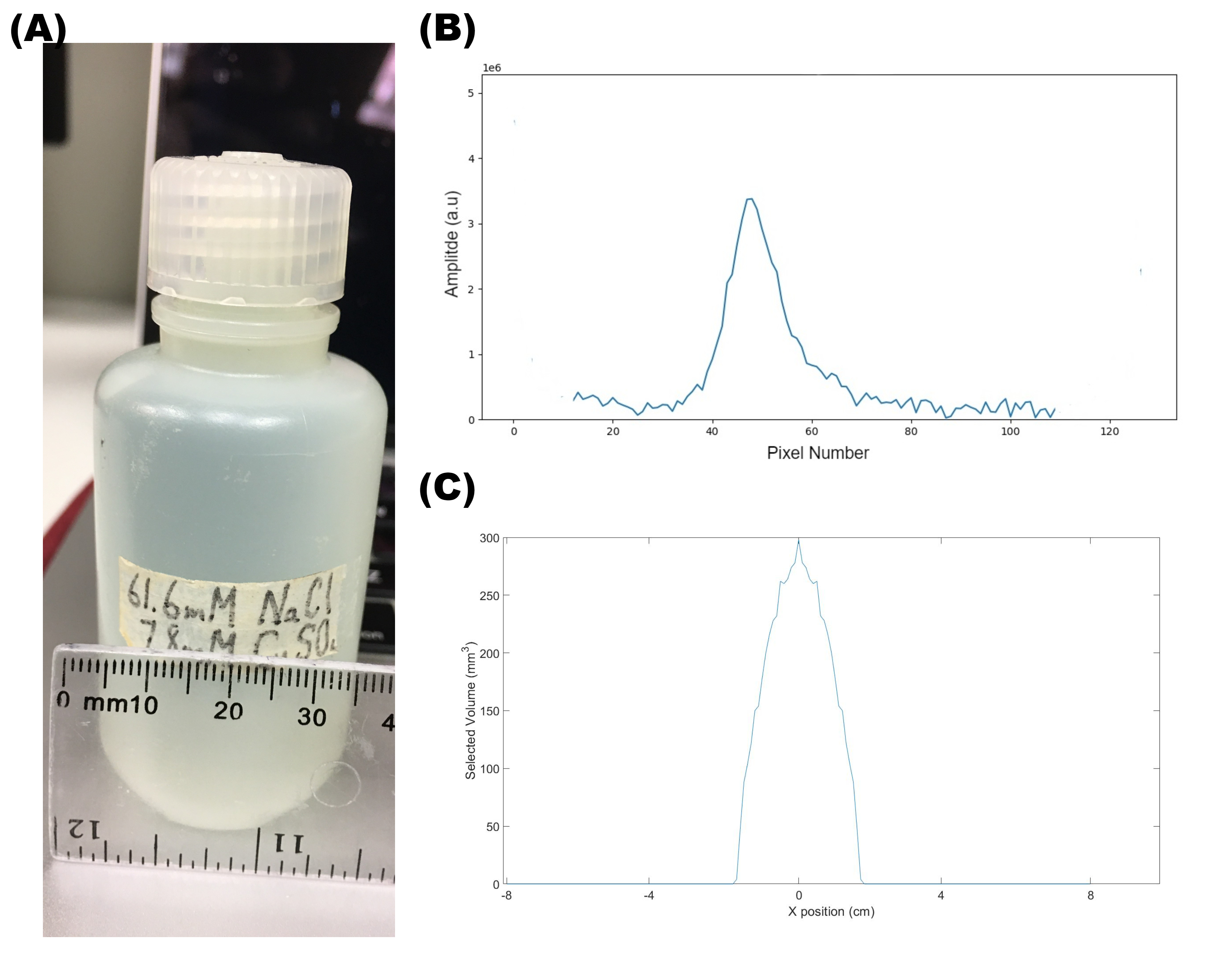
Figure 5: The one-dimensional TRASE experiment performed on a Halbach array. (A) 35mm diameter imaging phantom filled with tap water and doped with 61.6 mM NaCl and 7.8 mM CuSO4. (B) Obtained single-axis TRASE image. (C) Simulated expected excited volume based on the B0 pattern