5029
A Proposed Method for Retuning an RF Coil by Changing the Shield Radius for Multinuclear Imaging1Medical Biophysics, Western University, London, ON, Canada, 2Lawson Health Research Institute, London, ON, Canada, 3Physics and Astronomy, Western University, London, ON, Canada, 4School of Biomedical Engineering, Western University, London, ON, Canada
Synopsis
This study investigates the feasibility of changing the shield radius of an RF coil to shift the resonant frequency from 1H to 19F for multinuclear imaging. The method proposed in this investigation was verified by changing the resonant frequency of a 129Xe RF Coil a total of 1.18 MHz by changing the shield radius, allowing it to be used in a 2.9T Siemens MRI and a 3.0T GE MRI. It was found that altering the shield radius had similar effects on the resonant frequency as using a variable tuning capacitor, allowing for one coil to be compatible with multiple scanners.
Introduction
Since its introduction by Hayes in 1985, the birdcage design has been widely used in clinical MRIs as transmit and receive (Tx/Rx) coils due to their high RF (B1) field homogeneity and signal-to-noise ratio1. These coils are tuned to resonate at the Larmor frequency which is both field strength and nuclei dependent. For multinuclear imaging, this requires dual-tuned RF coils or the use of multiple RF coils, both methods being expensive to manufacture. In this work, we investigated a new method for changing the resonant frequency of a shielded RF coil by only changing the shield radius. This method was verified by changing the shield radius of an RF coil by 5 mm resulting in a resonant peak shift of 1.18 MHz, enough for a 129Xe coil to be used in different scanners. With the results from this investigation, we propose a method for building a dual-tuned coil for both 1H and 19F imaging at 2.89T using the proposed variable shield radius method (requiring a resonant peak shift of 7.10 MHz). This is possible due to the change in self and mutual inductances of the coil by altering the shield radius providing a viable method for tuning a coil while maintaining a highly homogenous B1 field at a lower cost.Methods
Used in this study was a commercial inductively-driven rat-sized quadrature RF coil (Morris Instruments, Ottawa, Canada) originally built for 129Xe imaging in a 3T GE MR 750 clinical scanner with a measured field strength of 3T(35.31 MHz)2. The coil was an 8 rung high-pass coil with a radius of 63 mm, a length of 190 mm, and a shield radius of 86 mm. Advanced Design System (ADS, Keysight Technologies) was used to simulate the S-parameters and determine the change in location of resonant modes while changing the radius of the shield.A field shift of 0.1T is required to reuse this coil in a 3T Siemens Biograph mMR PET/MRI scanner with a measured field strength of 2.9T. Thus the radius of the shield was adjusted in ADS to compensate for a shift in 0.1T (1.18 MHz). A new shield was manufactured using aluminum strips on a G10 sheet with the ability to change between the radii calculated in ADS. The shield is designed on a G10 sheet with a thickness of 0.58 mm where the height of the G10 is equal to the length of the coil, and the length of the G10 prior to being wrapped around the coil is equal to $$(((change in radius)/(G10 thickness))+(thickness of conductive shield))*(circumference of inner radius)$$
The coil was then tested in the two clinical scanners.
The following parameters were used for the thermally polarized xenon phantom scan at the 3T GE MR 750 scanner: $$FOV=30x30cm^2, Matrix size=20x32, Pixel size=9.4x9.4mm^2, TE/TR=2ms/5sec, BW=2kHz, RF pulse=90^0, signal averages=9$$
The following parameters were used for the xenon phantom scan at the 2.9T Siemens Biograph mMR PET/MRI Scanner: $$FOV=49x30cm^2, Matrix size=104x64, Pixel size=4.7x4.7mm^2, TE/TR=1.7ms/5sec, BW=5kHz, RF pulse=90^0, signal averages=9$$ A single slice 2D Gradient Recalled Echo sequence was used in both cases.
Using the same coil parameters and numerical methods to determine resonance peak shifts, ADS was used to compare the feasibility of changing the resonant frequency of a coil tuned for 1H to 19F. The radius of the shield was adjusted in ADS to compensate for a shift in 7.1 MHz moving from 1H to 19F resonance at 2.89T. The coil was then simulated in Sim4Life (ZMT Zurich MedTech) to observe the changes in field homogeneity as the radius of the shield was changed.
Results
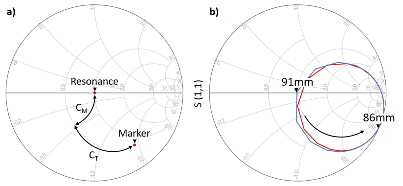
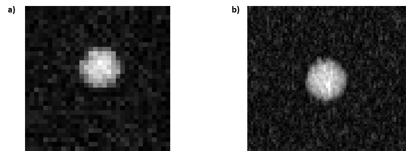
A change in radius from 86 mm to 91 mm was calculated in ADS to shift the resonance peak by 1.18 MHz. Figure 1 (a) shows the difference in resonance between the two shield radii. This shows that the coil can be tuned up to a total of 1.18 MHz by changing the radius of the shield by 5 mm. This change in resonant frequency can be observed on a Smith chart in Figure 2 showing a similar relationship to tuning capacitors. Figures 3 (a) and (b) show the xenon phantom images obtained at 3T and 2.9T scanners respectively. SNR calculated for the 3T scanner was 18.0 and SNR calculated for the 2.9T scanner was 16.0. This means that coil tuned for the 2.9T MRI scanner is 5.6 ((SNR2.9T/SNR3T)*(Pixel size2.9T/Pixel size3T)* ) times more efficient than when it was tuned for the 3T MRI scanner, keeping in mind that the same phantom and RF coil were used.The resonant frequency can be seen to decrease with an increase in shield radius. It was also observed that a shift in frequency of 7.1 MHz requires a change in shield radius of 5 mm when the same coil is tuned for 1H rather than 129Xe. With a shield thickness of 0.4 mm, the G10 cut out will need to be 9 times the circumference of the minimum shield radius. The results of this study show that using the variable shield as a method for tuning the coil can be used in the application of multinuclear imaging.
Acknowledgements
We acknowledge the support of the Natural Sciences and Engineering Research Council of Canada (NSERC), [funding reference number R5942A04]. We acknowledge the financial support received from BrainsCAN and Ontario Research Fund (ORF).
References
- Hayes CE, Edelstein WA, Schenck JF, Mueller OM, Eash M. “An Efficient, Highly Homogeneous Radiofrequency Coil for Whole-Body NMR Imaging at 1.5 T”. J. Magn Reson. 1985;63:622-628. doi:10.1016/0022-2364(85)90257-4
- Fox, M. S. et al. Detection of Radiation Induced Lung Injury in Rats Using Dynamic Hyperpolarized (129)Xe Magnetic Resonance Spectroscopy. Med Phys
41, 072302, doi:10.1118/1.4881523 (2014).
Figures