5026
MC-ECLIPSE for arbitrary ROI shaping and whole brain shimming for 3D MRSI1Radiology and Biomedical Imaging, Yale University, New Haven, CT, United States
Synopsis
ECLIPSE, a pulsed second order gradient insert can provide robust lipid suppression over an elliptical ROI for applications in human brain MRSI. While ECLIPSE provides excellent axial slice coverage for brain shapes that closely resemble an ellipse, coverage can be compromised for other head shapes. The development of an ECLIPSE gradient coil in combination with a 54-channel multi-coil array (MC-ECLIPSE), that allows B0 field shaping for arbitrary ROI generation is presented. Simulation results demonstrate that near-perfect (99%) axial slice coverage is achievable with MC-ECLIPSE, for a wide range of highly asymmetrical brain and head shapes.
Introduction
Magnetic Resonance Spectroscopic Imaging (MRSI) is a powerful technique that can map the metabolic profile in the brain non-invasively. Extracranial lipid contamination is, however, a hinderance that affects robust MRSI acquisitions, and compromises brain coverage following localization with linear gradients due to curvature of the brain. Recent work with a second order gradient insert (ECLIPSE1) provides robust extracranial lipid suppression with inner volume selection (IVS) and outer volume suppression (OVS) methods 2-3. While ECLIPSE provides excellent axial slice coverage for elliptical head shapes, coverage is reduced for highly asymmetrical head shapes. The development of an ECLIPSE gradient system with the addition of a 54-channel multi-coil array (MC-ECLIPSE) is presented, capable of providing arbitrary field shaping and whole brain shimming4 for applications in whole-brain 3D MRSI.Methods
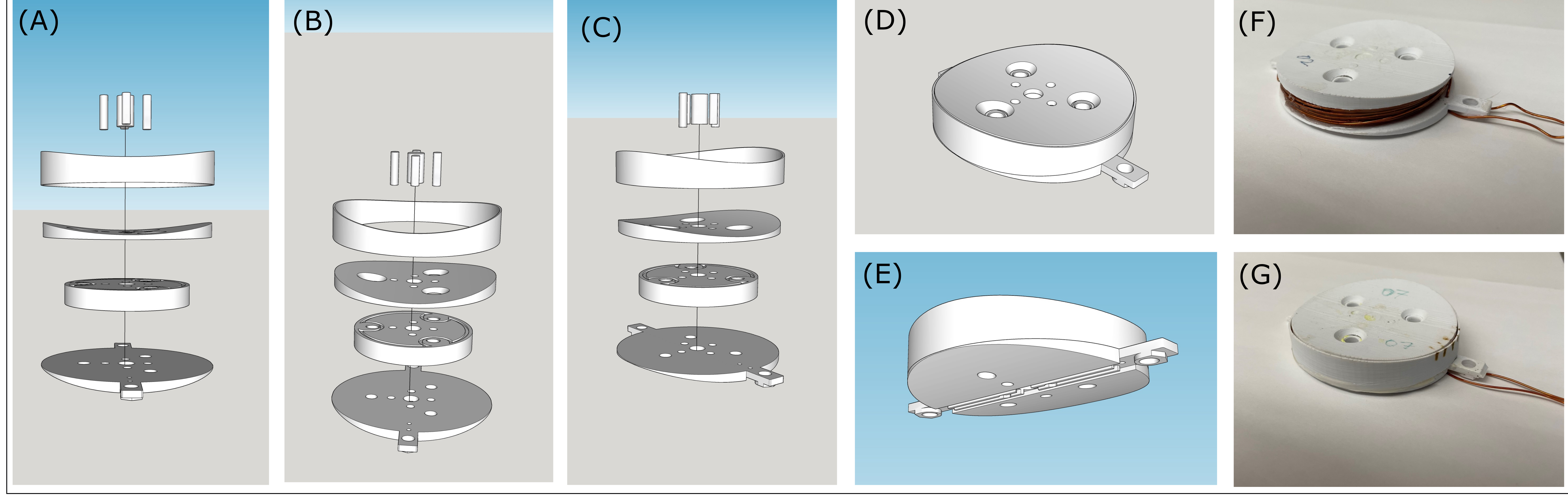
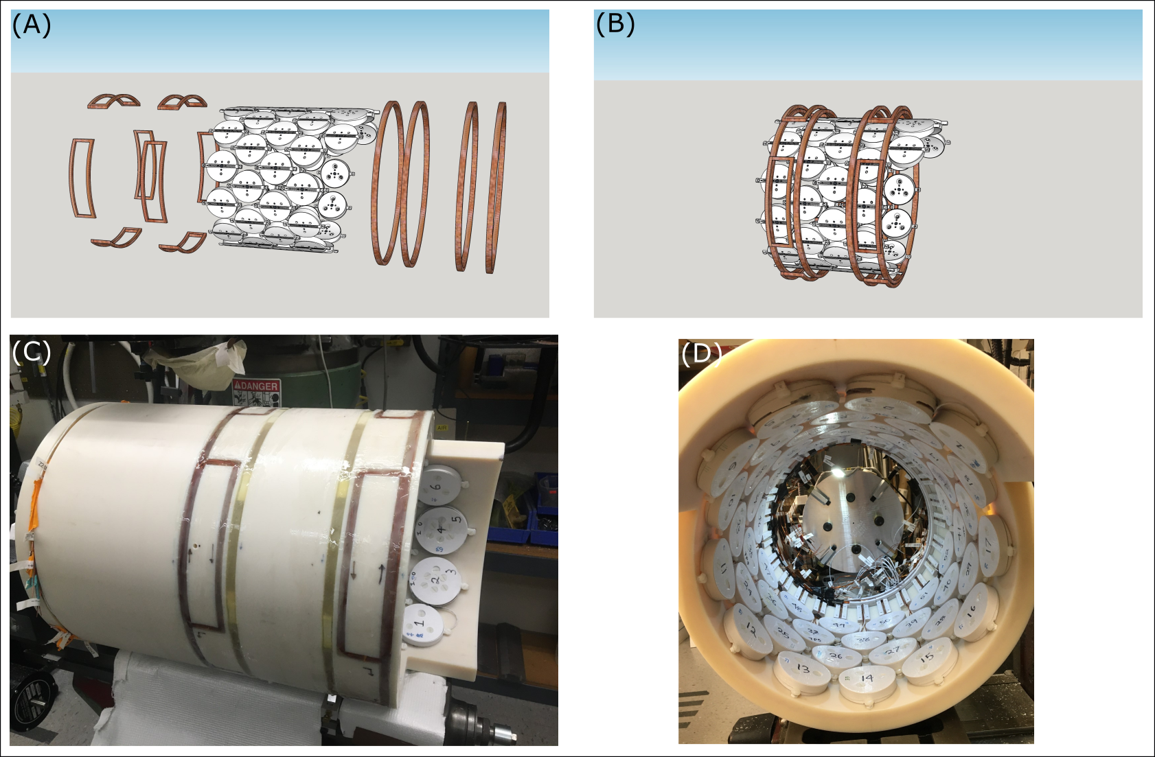
The 54-channel MC-array is modularly constructed with 3D printed ABS plastic as illustrated in Figure 1 A-E. The second order gradient coils and MC-array were populated on a nylon cylinder (The Plastic Factory, Bridgeport, CT, USA) with ID 376 mm and OD = 435 mm, and 660 mm length. The second order gradient coils consist of Z2 and X2Y2 wire tracks milled out on the OD of the nylon cylinder as previously described1, and the 54-channel MC-array was populated on the ID of the nylon cylinder (Figure 2). The MC-array consists of 48 elements with 70-mm diameter, with 12 elements per row and four layers (48 elements). The nylon cylinder has an extended cutout of 110 mm in length, populated with two 80-mm diameter and two 70-mm diameter MC elements, with the goal of improving B0 inhomogeneity in the ventral prefrontal cortex (Figure 2). The two 80-mm diameter MC elements consist of an inner coil with 40-mm diameter, and outer coil with 80-mm diameter, with 100-turns each, driven by two independent current amplifiers.All MR experiments will be performed on a 4T 94 cm Medspec scanner (Bruker corporation. Ettlingen, Germany) with gradients capable of switching 30mT/m in 1150µs. The ECLIPSE gradient coil is driven by Techron 7780 amplifiers (AE Techron, Elkhart, IN, USA) with 130V and 100A each, as described for the previous ECLIPSE system1. The 54-channel MC-array will be driven by 54 MXA current amplifiers capable of 2A per channel (Resonance Research Inc., MA, USA). The MC-ECLIPSE system will be controlled by a home-built multi-channel gradient controller5.
Theoretical B0 field maps were generated for each MC element based on the Biot-Savart law, knowing coil position, geometry, number of turns, and maximum current of 2A, to construct a basis set of fields used for subsequent fitting of desired field patterns for shaping (described next), and B0 shimming.
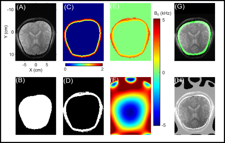
To generate arbitrary ROI shapes that can closely resemble the brain curvature, anatomical axial slab images acquired (Figure 3A) were segmented into brain (Figure 3B) and extracranial (Figure 3D) ROI’s. Next, a proof-of-concept arbitrary ROI generation method was developed using the following process. First, the outer rim of the brain ROI was repeatedly dilated five times to attain five layers of contours with increasing size that closely mimic the axial brain shape (Figure 3C). Next, each layer is assigned a desired B0 value starting from low to high, moving outwards (Figure 3E). Finally, a B0 fit is performed on the field pattern in Figure 3E using basis fields of the MC-ECLIPSE system, similar to B0 fitting of an acquired B0 map for shimming, to generate an experimentally feasible B0 field to allow localization over arbitrary brain shapes.
Results
The 70-mm diameter MC elements have a maximum resistance of ~1Ω and inductance of ~1.1mH and allows a ramp time of < 500 µs for all elements. However, all MC elements will be set to match the Bruker gradient ramp time of 1150 µs as currently used with ECLIPSE, for convenience in sequence programming.In the example of field shaping in Figure 3, the inner most layer was assigned a value of 1500 Hz, and the outer most layer was assigned a value of 3000 Hz (Figure 3E), leading to a desired gradient of ~ 1500 Hz/cm around the ROI or chemical shift displacement of 4 mm at the ROI edge. The fitted MC-ECLIPSE B0 field (Figure 3F) closely resembles the desired field as demonstrated by the ROI profile in Figure 3G. Here the thickness of the green ROI corresponds to a 600 Hz offset, or fat-water CSD at 4T.
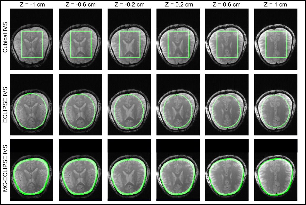
Figure 4 illustrates brain coverage achievable over a 2 cm slab with cubical selection, ECLIPSE localization, and MC-ECLIPSE localization. As expected, cubical selection provides the least favorable brain coverage of 60%, which is improved to 82% by ECLIPSE, consistent with previous work; in comparison, arbitrary shaping with MC-ECLIPSE achieves 99% coverage.
Discussion
Based on simulations, excellent brain coverage is achievable with MC-ECLIPSE localization for brain shapes that significantly deviate from elliptical or circular shapes. In this work 99% axial coverage is accomplished over a 2 cm slab with MC-ECLIPSE. Future work involves extending coverage along the Z-direction with improvements to the field shaping algorithm, and by employing multi-slab MC-ECLIPSE as demonstrated with ECLIPSE6.Acknowledgements
This research was supported by NIH grant R01- EB014861.References
[1] de Graaf RA, Brown PB, De Feyter HM, McIntyre S, Nixon TW. Elliptical localization with pulsed second-order fields (ECLIPSE) for robust lipid suppression in proton MRSI. NMR in biomedicine 2018;31(9):e3949.
[2] Kumaragamage C, De Feyter HM, Brown P, McIntyre S, Nixon TW, de Graaf RA. Robust outer volume suppression utilizing elliptical pulsed second order fields (ECLIPSE) for human brain proton MRSI. Magnetic Resonance in Medicine, 2020; 83(5):1539-1552.
[3] Kumaragamage C, De Feyter HM, Brown P, McIntyre S, Nixon TW, de Graaf RA. ECLIPSE utilizing gradient-modulated offset-independent adiabaticity (GOIA) pulses for highly selective human brain proton MRSI. NMR in Biomedicine 2020; 34:e4415.
[4] Juchem C, Nixon TW, McIntyre S, Boer VO, Rothman DL, de Graaf RA. Dynamic multi-coil shimming of the human brain at 7 T. Journal of Magnetic Resonance. 2011; 212:280-288.
[5] Nixon TW, McIntyre S, de Graaf RA. The design and implementation of a 64 channel arbitrary gradient waveform controller. Proc Int Soc Magn Reson Med. 2017;25:969.
[6] Kumaragamage C, Brown PB, McIntyre S, Nixon TW, De Feyter HM, de Graaf RA. Multi-slab 3D ECLIPSE for whole brain lipid suppressed MRSI. Int Soc Magn Reson Med. 2022 [submitted].
Figures