5010
Elliptical Field-of-Views in Radial T2 mapping1Medical Imaging, The University of Arizona, Tucson, AZ, United States, 2Electrical and Computer Engineering, The University of Arizona, Tucson, AZ, United States, 3Siemens Medical Solutions USA Inc, The University of Arizona, Tucson, AZ, United States, 4Biomedical Engineering, The University of Arizona, Tucson, AZ, United States
Synopsis
Radial imaging is appealing for quantitative parameter mapping, due to their inherently robustness to undersampling compared to Cartesian trajectories and thus, its ability to yield parameter maps with high spatial resolution from highly undersampled data. Two-dimensional radial imaging typically acquires equiangular spaced lines, resulting in a circular field-of-view (FOV). Circular FOVs are not ideal for imaging applications with an anisotropic region-of-support (e.g., spine, leg). Larson et al. proposed an algorithm for designing fully sampled radial trajectories matching the prescribed anisotropic FOV. In this work we investigate the benefits of anisotropic FOV in radial MRI in the context of parameter mapping.
Introduction
Radial imaging is appealing for quantitative parameter mapping [1-2], due to their inherently robustness to undersampling compared to Cartesian trajectories and thus, its ability to yield parameter maps with high spatial resolution from highly undersampled data. Moreover, the continuous sampling of the center of k-space in radial trajectories allows for parameter mapping with high temporal resolution. Two-dimensional radial imaging typically acquires equiangular spaced lines, resulting in a circular field-of-view (FOV). Circular FOVs are not ideal for imaging applications with an anisotropic region-of-support (e.g., spine, leg). Larson et al. [3] proposed an algorithm for designing fully sampled radial trajectories matching the prescribed anisotropic FOV. Wu et al. [4] tailored Larson’s algorithm to support undersampling and golden angle view ordering. In this work we investigate the benefits of anisotropic FOV in radial MRI in the context of parameter mapping.Methods
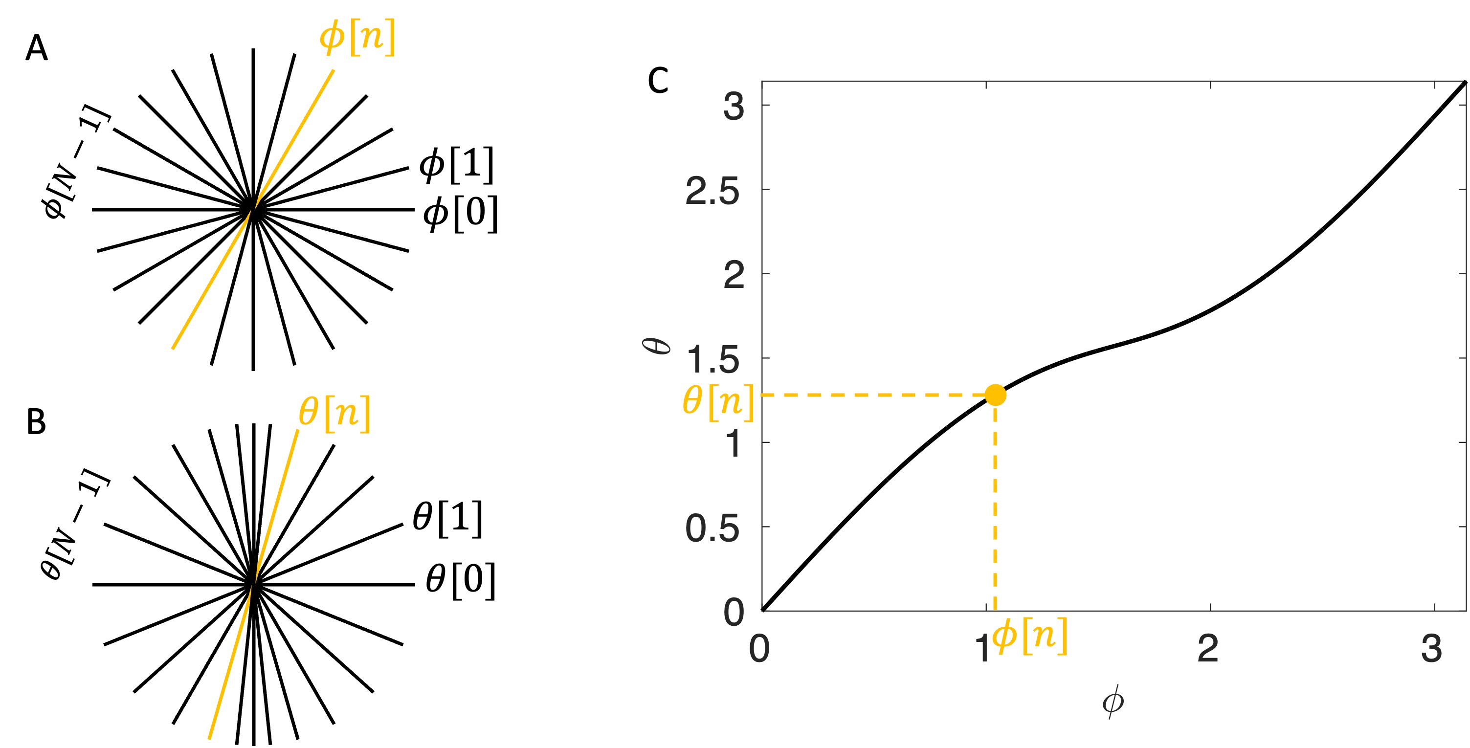
In this work, elliptical FOV is achieved by variable angular spacing denoted as $$$\Delta\theta(\cdot)$$$ with a constant k-space extent denoted as $$$k_{max}$$$ to maintain isotropic resolution. Figure 1 illustrates the proposed implementation in k-space and image space. At an arbitrary angle $$$\phi$$$ in k-space, the separation at the end of the projection $$$\Delta k_\phi(\phi)$$$ is inversely related to FOV at $$$\phi+\pi/2$$$, according to Fourier transform, that is$$\Delta k_\phi(\phi)=[FOV(\phi+\pi/2)]^{-1}.$$
The variable angular spacing $$$\Delta\theta(\phi)$$$ can be approximated and expressed as (for small angles)
$$\Delta(\phi) \approx \Delta k_\phi(\phi)/k_{max}=[k_{max}FOV(\phi+\pi/2)]^{-1}.$$
FOV$$$(\phi)$$$ can be analytically computed given the major axis length $$$a$$$ and minor axis length $$$b$$$ of an elliptical FOV. $$$\Delta(\phi)$$$ can be expressed using $$$a$$$ and $$$b$$$ as follows
$$\Delta(\phi) = \sqrt{a^2/cos^2(\phi+\pi/2) + b^2/sin^2(\phi+\pi/2)}$$
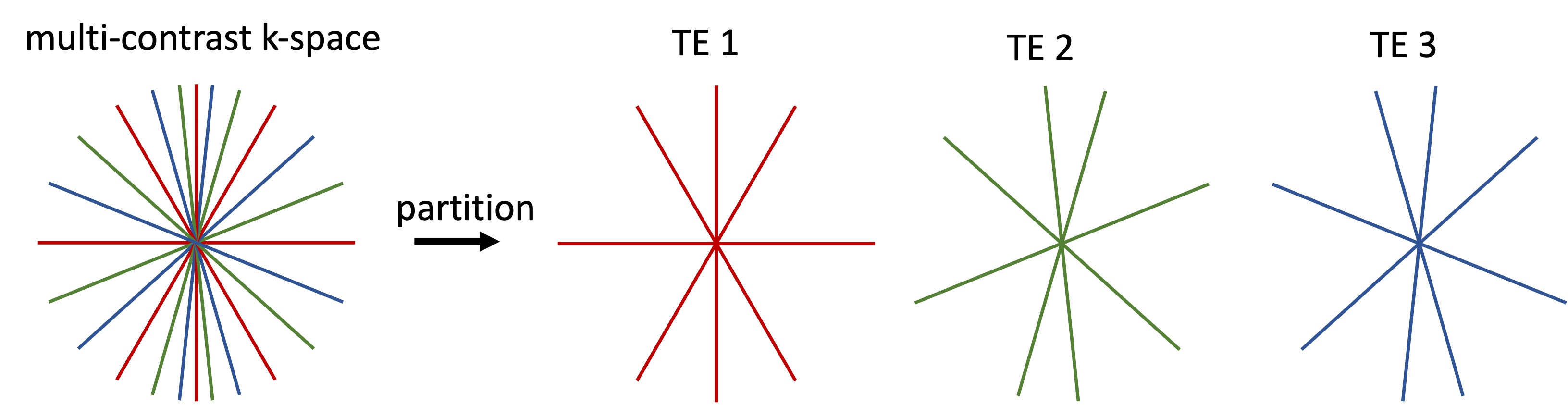
where the constant is set to 1. Without loss of generality, the design of radial trajectory always starts from with angular coverage of using N spokes. One can gradually accumulate to obtain and build a look up table (LUT) relating and , shown as a curve ranging from to in Figure 2A. Figure 2B and 2C show an k-space sampled by twelve radial lines with equiangular space and variable angular spacing, respectively. Note that the th radial lines in Figure 2B and 2C yield a one-to-one mapping in the LUT or the curve. To suit the implementation to parameter mapping sequence, the entire multi-contrast k-space is first design using the LUT and further partitioned (by line index) to each TE according to specific view orderings. Figure 3 shows a partition of 12-line multi-contrast k-space using a pseudo golden angle (pGA) view ordering [5].
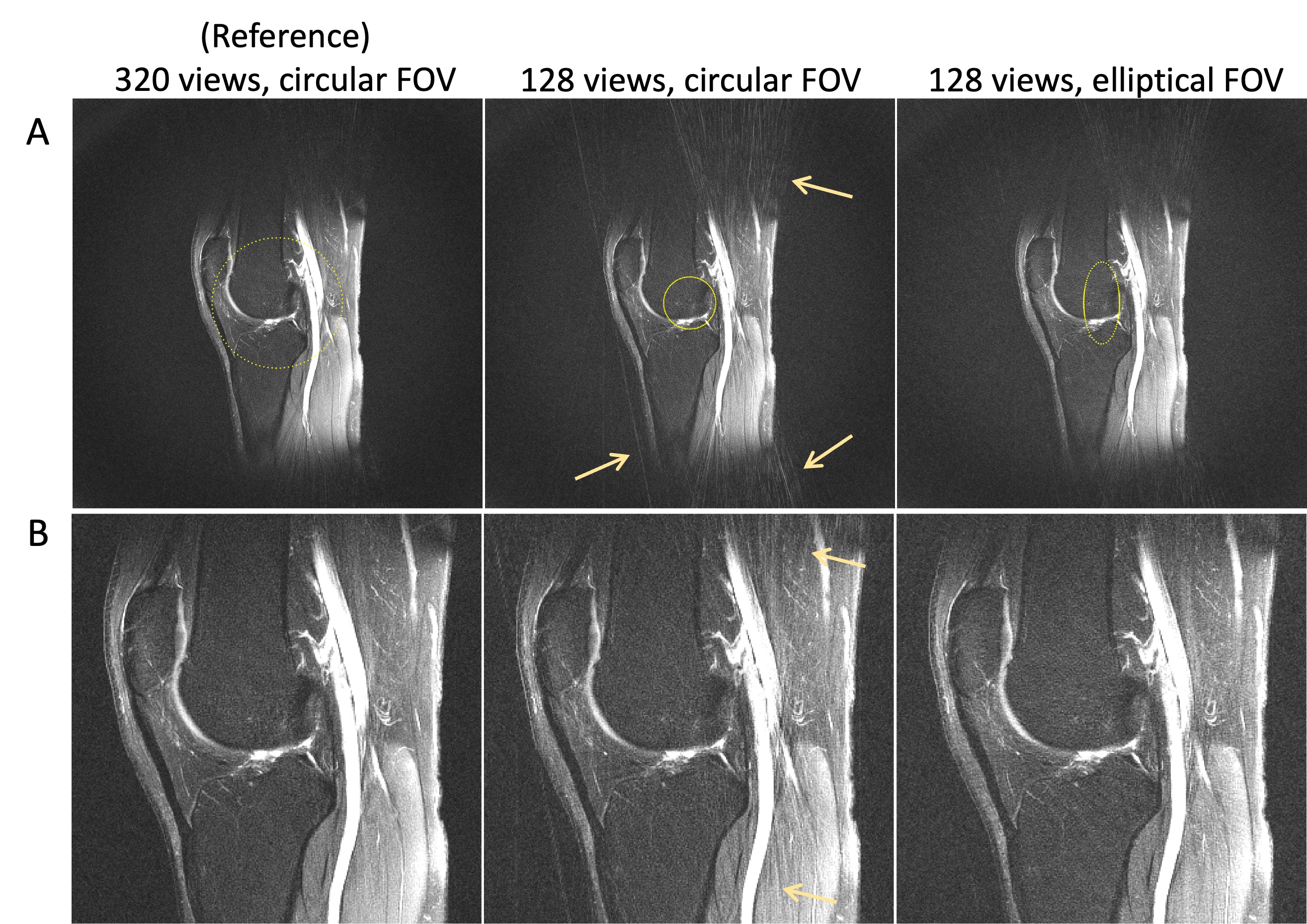
The proposed radial trajectory design was integrated into a radial turbo-spin echo RADTSE [5] sequence to support elliptical FOV and implemented to a Siemens, Skyra scanner. In vivo RADTSE data were acquired on the knee of normal volunteers in the sagittal plane using a 15-channel knee coil. The common sequence parameters are TR/TE = 3.28 s/13 ms, FOV = 16 cm, 320 readout points, and echo train length of 8 using pGA view ordering. Highly undersampled data were acquired with two times averages at 128 views and prescribed with circular and elliptical FOV (ratio=0.44), respectively. A reference scan was acquired with circular FOV at 320 views. These three RADTSE datasets underwent the same reconstruction procedure: (i) all radial views were used to reconstruct an anatomical image with an average TE contrast, i.e., the composite image; (ii) a model-based iterative algorithm [6] was used to reconstruct TE images, which were fitted using VARPRO [7] to obtain the T2 map.
Results
Figure 4 shows the composite images of a representative knee slice. On the top row, the unaliased FOV (dotted contour) are shown on the composite images at twice the prescribed FOV. Compared to the reference and the image with proposed elliptical FOV, the image with circular FOV contains a visibly larger amount of aliasing artifacts due to undersampling (yellow arrows). On the bottom, composite images are shown at the prescribed FOV. The image with circular FOV suffers from noticeable streaks in the vertical direction (arrows), which are greatly reduced or not visiable in the image with elliptical FOV yet at the same undersamling rate. It is worthy noting that these streaks can mimic vessel-like structures and obscure the underlying muscle anatomy.Figure 5 show TE images and T2 maps of another representative knee slice. Undersampling streaks through the bone can be observed on the TE images with circular FOV (yellow arrow) but not on the reference image or the image acquired with elliptical FOV. In the T2 maps with circular FOV, the undersampling artifacts are shown as shading (red arrow), streaks (white arrow), and noise amplification (yellow arrow), resulting in poor T2 estimation or obscured anatomy structure. Compared to the reference T2 map, these artifacts are well-suppressed in the T2 map with elliptical FOV due to a better tailoring to the knee anisotropic dimension.
Conclusion
We proposed a projection design method that supports elliptical FOVs for radial parameter mapping. In vivo knee experiment shows reduced undersampling artifacts in the image and T2 maps when imaged with elliptical FOV compared to circular FOV.Acknowledgements
The authors would like to acknowledge support from NIH (grant R01CA245920), the Arizona Biomedical Research Commission (Grant ADHS14-082996), and the Technology and Research Initiative Fund (TRIF) Improving Health Initiative.References
1. Keerthivasan, M. B., Galons, J. P., Johnson, K., Umapathy, L., Martin, D. R., Bilgin, A., & Altbach, M. I. (2021). Abdominal T2‐Weighted Imaging and T2 Mapping Using a Variable Flip Angle Radial Turbo Spin‐Echo Technique. Journal of Magnetic Resonance Imaging.
2. Li, Z., Bilgin, A., Johnson, K., Galons, J. P., Vedantham, S., Martin, D. R., & Altbach, M. I. (2019). Rapid high‐resolution T1 mapping using a highly accelerated radial steady‐state free‐precession technique. Journal of Magnetic Resonance Imaging, 49(1), 239-252.
3. Larson, P. E., Gurney, P. T., & Nishimura, D. G. (2007). Anisotropic field-of-views in radial imaging. IEEE transactions on medical imaging, 27(1), 47-57.
4. Wu, Z., Han, F., Hu, P., & Nayak, K. S. (2016). Anisotropic field‐of‐view support for golden angle radial imaging. Magnetic resonance in medicine, 76(1), 229-236.
5. Altbach, M. I., Outwater, E. K., Trouard, T. P., Krupinski, E. A., Theilmann, R. J., Stopeck, A. T, & Gmitro, A. F. (2002). Radial fast spin‐echo method for T2‐weighted imaging and T2 mapping of the liver. Journal of Magnetic Resonance Imaging, 16(2), 179-189.
6. Tamir, J. I., Uecker, M., Chen, W., Lai, P., Alley, M. T., Vasanawala, S. S., & Lustig, M. (2017). T2 shuffling: sharp, multicontrast, volumetric fast spin‐echo imaging. Magnetic resonance in medicine, 77(1), 180-195.
7. Golub, G., & Pereyra, V. (2003). Separable nonlinear least squares: the variable projection method and its applications. Inverse problems, 19(2), R1.
Figures