4923
A novel patient-adjustable coil technology substantially reduces RF heating of cardiac implantable electronic devices in pediatric patients1Northwestern University, Chicago, IL, United States, 2TH Mittelhessen University of Applied Sciences, Giessen, Germany, 3Massachusetts General Hospital, Charlestown, MA, United States, 4Lurie Children's Hospital, Chicago, IL, United States
Synopsis
Infants and children with congenital heart disease may require cardiovascular implantable electronic devices (CIEDs), which typically precludes future evaluation by MRI due to risks associated with RF heating of implants. Here we demonstrate that a novel concept based on patient-adjustable rotating RF coil technology that was originally developed to reduce RF heating of brain implants can be adopted in pediatric patients with CIEDs to substantially reduce RF heating. Our simulations in a cohort of children with both epicardial and endocardial devices showed an 87% reduction in average SAR compared to conventional body coils.
Introduction
Infants and children with congenital heart disease (CHD) often require cardiovascular implantable electronic devices (CIED)1. Some infants receive CIED within hours, or even minutes, of birth2. Unfortunately, once CIEDs have been implanted, there is a relative contraindication for MRI exam due to risks of RF heating of the device. Recently, an RF coil technology based on a patient-adjustable rotating transmit coil was shown to reduce RF heating of neurological implants in adult patients3-6. Here we show that this novel concept can be adopted in children with CIEDs. We designed and constructed a linearly polarized (LP) mechanically rotating birdcage transmitter for MRI of children (0-3 y/o) in a 1.5 T scanner. The coil is a 16-rung low-pass birdcage and has a slab-like region of very low electric field which can be steered by mechanically rotating the coil around patient’s body. Once the coil is positioned at its optimum angle for an individual patient, i.e., the angle at which patient’s implanted device is maximally contained within the low E field region of the coil, the local SAR amplification around the implanted lead tip is virtually eliminated. The SAR-reduction performance of the coil was assessed in electromagnetic simulations in 10 patient-derived realistic models of CIEDs with both endocardial and epicardial leads. The mean reduction in the 0.1g-averaged SAR was 87 % (> 7 fold). A prototype of the rotating coil is built and will be tested on a commercial CIED (Medtronic Azure XT DR) implanted in an anthropomorphic pediatric phantom to validate simulation results.Methods
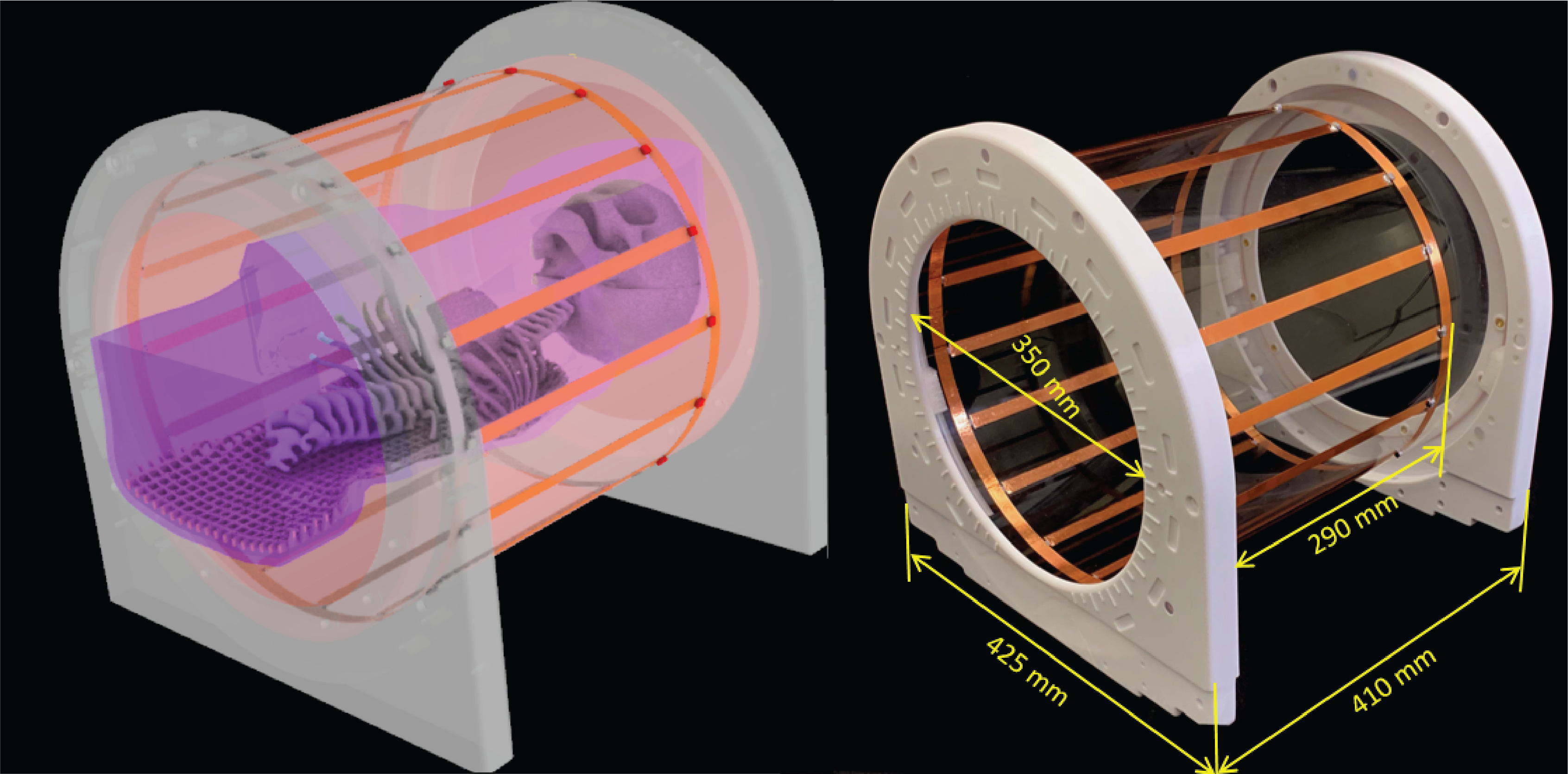
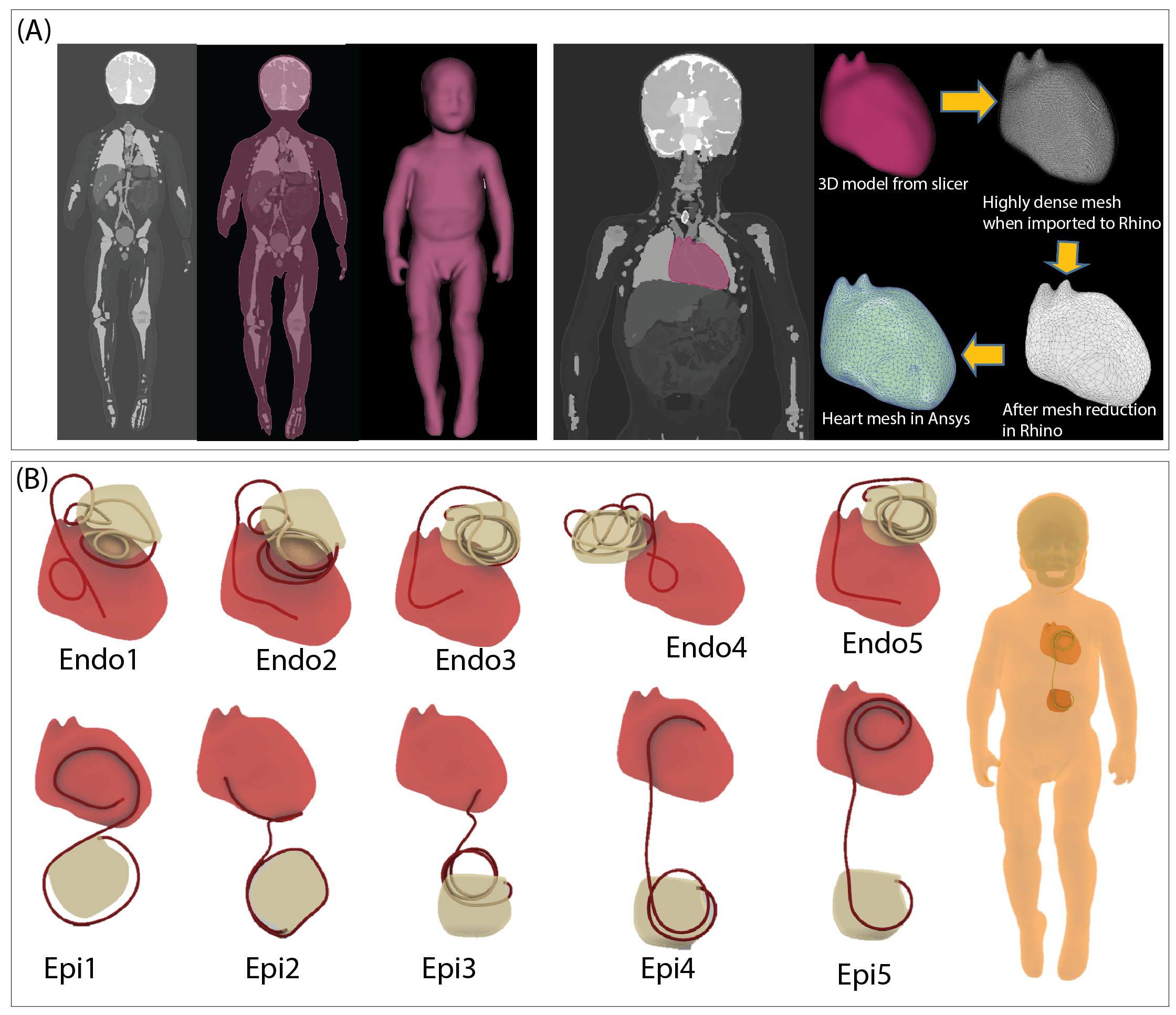
Rotating coil: A linearly polarized 16-rung lowpass birdcage coil was constructed on a 350 mm diameter acrylic cylinder (Figure 1). The coil’s ladder network was constructed from 12 mm adhesive copper tape (Chomerics Inc., Woburn,MA,USA) and had a rung length of 290 mm. Two mechanical annuli were secured to the birdcage ends and rested on four guide wheels located on a sliding frame, allowing the birdcage to rotate freely around its axis without touching the load.Simulations: A child body model was created from segmented MRI images of a 29-months-old child7. Segmented images were manually smoothed and closed 3D surfaces representing average tissue, skull, brain, and heart were created in a CAD tool (Rhino 7, Robert McNeel and Associates, Seattle). Ten unique CIED lead trajectories consisting of 5 epicardial and 5 endocardial cases were created based on X-ray images of pediatric patients with CIEDs and incorporated in the body model (Figure 2).
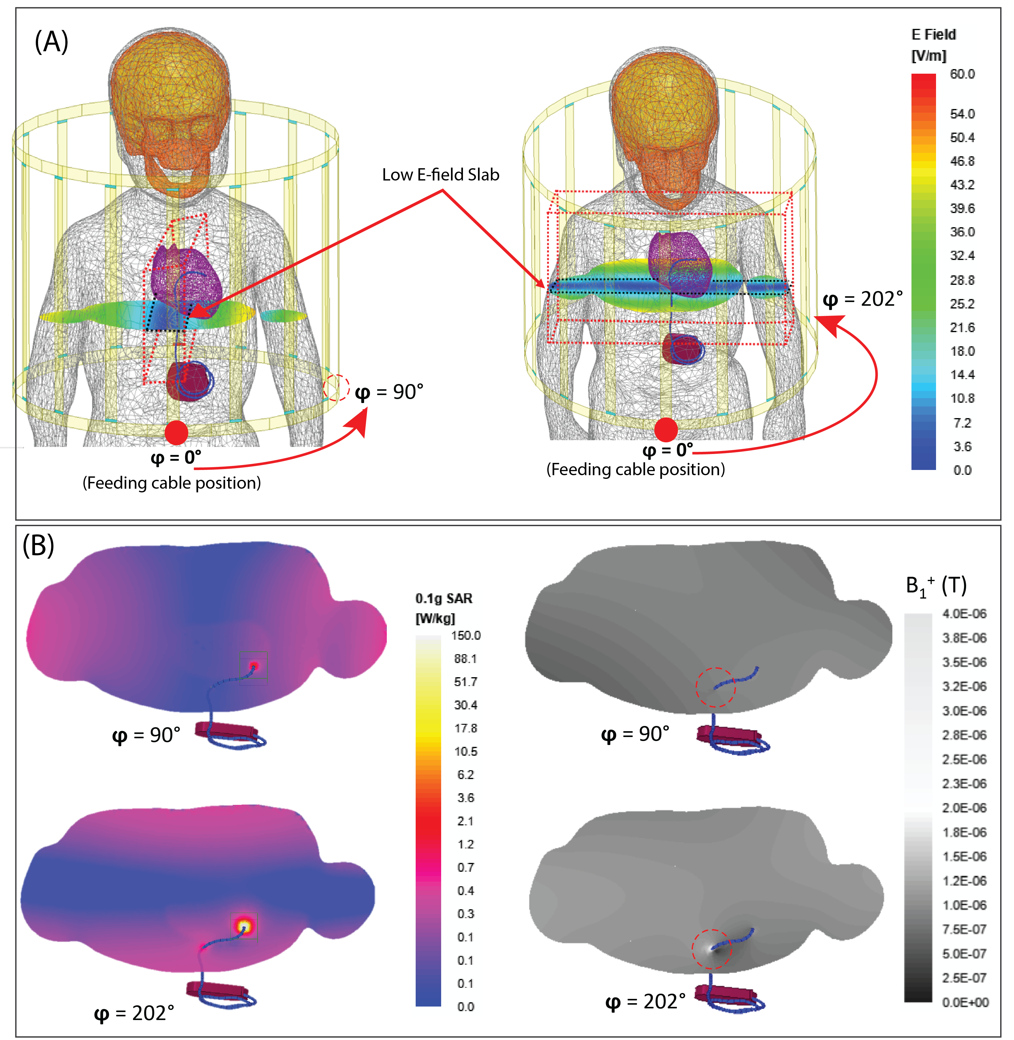
Electromagnetic simulations were implemented in ANSYS Electronic Desktop 2021 R1 HFSS (ANSYS Inc., Canonsburg, PA). Model of a local birdcage transmit coil with dimensions matching the constructed prototype was created and tuned to 64 MHz. The coil was fed with a single cable connected to the bottom end ring which generated a linearly polarized B1 field and an E field with a slab-like region of low intensity, which was then steered by rotating the coil around the body at 22.5° increments (16 positions in total) (Figure 3). The simulations were repeated with a conventional body coil (50 cm length, 71 cm diameter) in circular polarization (CP). Coil SAR-reduction performance was quantified by a SAR Reduction Efficiency (SRE) metric calculated as
$$$%$$$SREn(φ) $$$=$$$ $$$100×$$${Max0.1gSARCP,n $$$-$$$Max0.1gSAR(φ)LP,n}$$$/$$$Max0.1gSARCP,n
where Max0.1gSARCP,n was the maximum of 0.1g-averaged SAR at the tip of the CIED lead 'n' produced by a CP body coil whereas Max0.1gSAR(φ)LP,n was the maximum of 0.1g-averaged SAR produced by the rotating LP coil at rotational angle $$$φ ε [0° - 360°]$$$.
Results
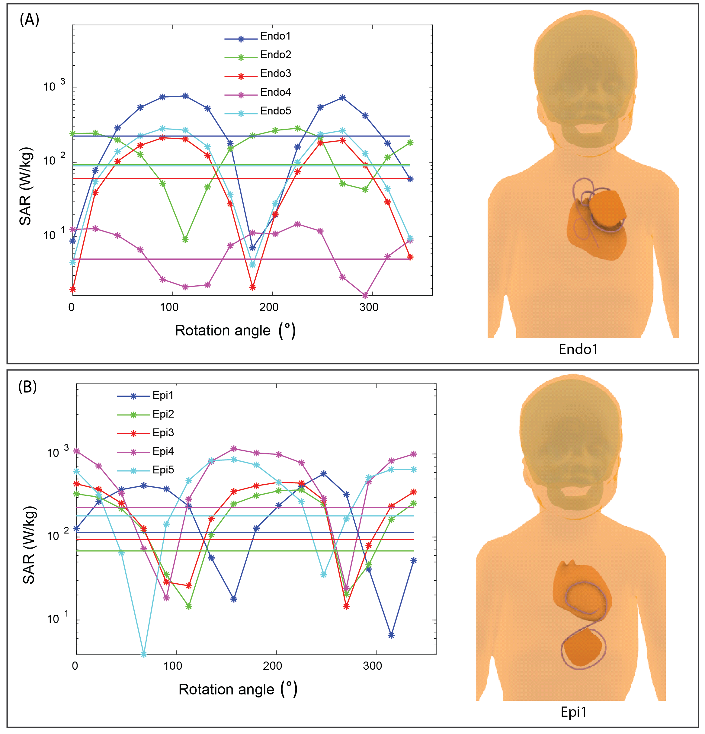
SAR reduction performance: For all device configurations, we were able to find an optimum rotation angle that reduced the SAR at tips of implanted leads well below SAR levels produced by a CP body coil, even when the input power of both coils were adjusted to produce the same B1+ (2μT) at the iso-center (Figure 4 & 5). The SRE ranged from 58% to 98% with an average of 87% which is equivalent to > 7-fold reduction in SAR. The position of the optimum angle could be reliably determined from B1+ maps as they corresponded to a minimized RF-induced B1-inhomogeneity around the lead (Figure 3).Sensitivity to operational error: The safety margin of the coil was quantified with a metric of Permissible Rotational Error (PRE) defined as
PREn $$$=$$$|φn,opt$$$-$$$φn,CP|
where φn,opt is the optimum angle that minimizes the SAR for lead 'n', and φn,cp is the the nearest angle from optimum angle at which the SAR due to rotating coil equals that of CP body coil. PRE was found to be 25° ± 7.9°, which is substantially higher than the rotational resolution of the coil (5°), indicating that risks due to operational error could be kept at minimum.
Discussions and Conclusions
Application of a new coil technology for full body MRI of infants and children (<3 y/o) with CIEDs was demonstrated. The constructed local transmit coil fits inside a 50-cm bore magnet and can be rotated smoothly around the child’s body to an optimum angle that virtually eliminates implant RF heating. Position of the optimum angle can be reliably determined by minimizing the B1-inhomogeneity around the lead on B1+ maps using a low-SAR B1 mapping sequence.Acknowledgements
No acknowledgement found.References
1. Epstein A. American College of Cardiology/American Heart Association Task Force on Practice Guidelines (Writing Committee to Revise the ACC/AHA/NASPE 2002 Guideline Update for Implantation of Cardiac Pacemakers and Antiarrhythmia Devices); American Association for Thoracic Surgery; Society of Thoracic Surgeons. Circulation. 2008;117:e350-e408.
2. Taşar M, Yaman ND, Arıcı B, et al. Minimally invasive permanent pacemaker implantation immediately after birth: from delivery room to heart surgery: Permanent Pacemaker Implantation in First Month of Life. 2021:1-3.
3. Golestanirad L, Keil B, Angelone LM, et al. Feasibility of using linearly polarized rotating birdcage transmitters and close‐fitting receive arrays in MRI to reduce SAR in the vicinity of deep brain simulation implants. Magnetic resonance in medicine. 2017;77(4):1701-12.
4. Kazemivalipour E, Keil B, Vali A, et al. Reconfigurable MRI technology for low-SAR imaging of deep brain stimulation at 3T: Application in bilateral leads, fully-implanted systems, and surgically modified lead trajectories. NeuroImage. 2019;199:18-29.
5. Bhusal B, Keil B, Rosenow J, et al. Physics in Medicine and Biology. Patient’s body composition can significantly affect RF power deposition in the tissue around DBS implants: ramifications for lead management strategies and MRI field-shaping techniques. 2021;66(1):015008.
6. Golestanirad L, Iacono MI, Keil B, et al. Construction and modeling of a reconfigurable MRI coil for lowering SAR in patients with deep brain stimulation implants. Neuroimage. 2017;147:577-88.
7. Jeong H, Ntolkeras G, Alhilani M, et al. Development, validation, and pilot MRI safety study of a high-resolution, open source, whole body pediatric numerical simulation model. 2021;16(1):e0241682.
Figures