4828
Evaluation of 3D Tailored Excitation Sequences on the MRI Safety Assessment of Transvenous Implantable Pacemaker, ICD or CRT System1Abbott Laboratories, Sylmar, CA, United States
Synopsis
A 3D tailored excitation sequence at 3T was found to have peak RF simultaneous with gradient slewing. The exposure levels generated by this sequence were determined and impact to the transvenous implantable pacemakers, implantable Cardioverter Defibrillators (ICDs) and Cardiac Resynchronization Therapy (CRT) systems safety evaluation of RF and gradient voltages was assessed. It is demonstrated that the combined RF and gradient level is expected to be covered by the separate RF and gradient test level required by ISO/CD 10974, and the bandwidth of the 3D sequence is well within the frequency ranged specified in ISO/CD 10974.
Background
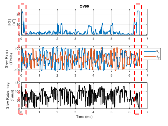
Sequences using 3D tailored excitation have been reported [1]. As shown in Fig 1 these sequences generate atypical RF and gradient waveforms.MRI safety assessment of active implantable medical devices (AIMD) use methods from ISO/CD 10974. These methods evaluate the hazard of device damage, malfunction and unintended tissue stimulation in response to RF exposure and also in response to gradient exposure. The rationale for the separation of the RF and gradient evaluations is that typically the gradient is not slewing at the same time as the RF is active, and in those cases where it may, the strength of the RF and gradient is not at maximum. There may also be a separation in the landmarks which generate the maximum strength RF and gradient, for example a pacemaker would have a worst-case RF landmark around the chest whereas the worst case gradient landmark would occur around the head. For implants labeled to 3T with a gradient slew rate of 200T/m/s, ISO/CD 10974 test method require testing to a peak B1+ of 27uT and slew rate of 200T/m/s. In addition, the RF frequency range evaluated for 3T scanners is specified in the draft ISO/CD 10974 as 127.7 MHz ± 5 %. There is motivation to evaluate if there is any impact of 3D tailored excitation sequences to the current state of the art in AIMD MRI safety assessment, either from the overlapping of gradient slewing with high RF and/or the bandwidth of the RF pulses.
Methods
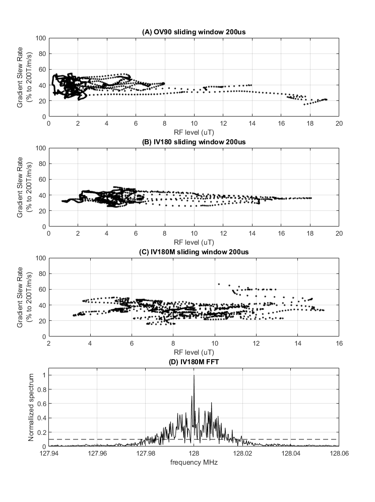
An FFT was performed on the RF pulse and compared to the frequency range used for implant safety evaluations.The gradient slew rate magnitude was calculated as $$$\sqrt{G_x^2+G_y^2}$$$. Only X and Y components were used in the calculation for transvenous CRM (Cardiac Rhythm Management) devices per ANSI/AAMI PC76:2021. The RF and gradient slew magnitude waveforms were then averaged with a sliding window length of 200us using a 4us step size. The point-by-point pairs of RF peak B1+ and gradient magnitude were plotted.
The impact of the separation in landmark where the RF and gradient are maximized was evaluated. A 65cm commercial cardiac lead RF voltage transfer function for 27uT peak B1+ was combined with Etans extracted along implant pathways from an Obese male body model for landmarks of z=0cm to z=50cm where z=0cm is defined as eye level. The ISO/CD 10974 Gradient Tier 3 method was used to calculate the gradient voltage for 200T/m/s gradient slew rate for a 65cm cardiac lead along the same implant pathways, body model and landmarks. The landmarks that generated the maximum RF and gradient voltages was determined.
Results
The FFT for each of the three RF pulses was calculated. The largest bandwidth was found for the IV180M pulse with frequency content between 127.98MHz and 128.02MHz [Fig 2D].The maximum RF peak B1+ reached was 19.1uT which occurred with a gradient slew of 43.4T/m/s [Fig 2A]. The maximum gradient slew was 133T/m/s which occurred with a RF peak B1+ of 10.2uT [Fig 2C].
The highest RF voltage was generated at the z=30cm landmark where the chest is in the center of the coil. And the highest gradient voltage was generated at the z=0 landmark where the eyes are in the center of the coil. The reduction in RF voltage going from z=30cm to z=0cm was found to be 36%. The reduction in gradient voltage going from z=0cm to z=30cm was found to be 46%.
This means that due to separation in worst case landmarks for RF and gradient, the maximum RF peak B1+ reached is expected to be 19.1uT simultaneous with a gradient voltage of 11.7% of max. Similarly, the maximum gradient slew of 134T/m/s reached is expected to be simultaneous with an RF voltage of 24% of max.
Conclusion
It is expected that the separate testing of RF at 27uT and gradient at 200T/m/s is sufficient to cover the levels generated by this sequence since the maximum tested RF or gradient level are not reached individually and are limited to simultaneous exposures of 11% of max gradient voltage and 24% of max RF voltage.The RF pulse bandwidth is within the 127.7 MHz ± 5 % tolerance specified in ISO/CD 10974 draft.
Acknowledgements
KF and SS would like to thank Dr Tianrui Luo for providing the 3D tailored excitation pulses used in this analysis.References
1) Luo, Tianrui et al. “Joint Design of RF and gradient waveforms via auto-differentiation for 3D tailored excitation in MRI.” IEEE transactions on medical imaging PP (2021): n. pag.
2) ISO/CD 10974 Assessment of the safety of magnetic resonance imaging for patients with an active implantable medical device
3) ANSI/AAMI PC76:2021 Active implantable medical devices—Requirements and test protocols for safety of patients with pacemakers and ICDs exposed to magnetic resonance imaging
Figures