4827
MRI Gradient Induced Device Heating of Leadless Pacemakers1Abbott, Sylmar, CA, United States, 2Abbott, Sunnyvale, CA, United States
Synopsis
Simulations and benchtop testing were performed to assess potential gradient induced device heating of leadless pacemakers. Results of the evaluation showed leadless pacemakers sized objects, made from commonly used conductive materials, heated less than 1°C when exposed to the gradient induced device heating safety test conditions per ISO/TS 10974. In general, a temperature rise less than 2°C is considered to be clinically insignificant. As such, the risk of leadless pacemaker gradient induced device heating is negligible and assessments for this hazard per ISO/TS 10974 may not be necessary.
Introduction
For the assessment of MR conditional safety there are many hazards to consider. Gradient induced device heating is one hazard identified in ISO/TS 10974. The imaging gradient dB/dt field can induce eddy currents on the conductive surfaces of an of Active Implantable Medical Device (AIMD) resulting in heating. The instantaneous power deposited by a dB/dt field into a conductive material is proportional to its size1, where larger objects of the same material will have higher heating and smaller objects will have less heating.As leadless pacemakers are relatively small AIMDs, we explore in this abstract the potential gradient induced heating for this type of device by modeling and conducting benchtop testing on leadless pacemaker sized objects made from commonly used conductive materials. The results from this modeling and testing are then evaluated to see if the temperature rises could result in clinically significant heating.
Methods
To assess potential gradient induced heating of leadless pacemakers, simulations were performed using COMSOL Multiphysics software (v5.6). These simulations were conducted on leadless pacemaker sized objects (solid cylinders with a length of 38mm and diameter of 6.65mm) constructed from materials commonly used in the large conductive surfaces of AIMDs (Titanium, MP35NLT, Tantalum, Lithium, CFx, Pt-Ir, Nickel, Aluminum).The simulations were set up to emulate exposure to the gradient induced device heating safety test per ISO/TS 10974, where the test object is placed inside a tissue simulating gel solution (1.2 S/m HEC) and then exposed to a changing magnetic field of 42T/s RMS using a sine waveform with a frequency of 1750Hz for a total of 15 minutes per exposure.
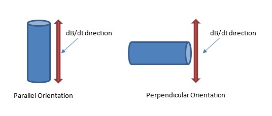
An initial set of simulations was conducted on a Titanium object to determine the orientation with respect to the changing magnetic field, parallel vs perpendicular (see Figure 1), which generates the largest heating. Titanium was selected for this simulation as it is the most commonly used material for AIMD enclosures.
Once the worst-case orientation was determined, simulations were conducted on all the materials specified above to determine the worst-case heating for each material.
To validate the simulation results, MR gradient induced heating testing was performed on three of the modeled materials: Titanium, Nickel, and Aluminum. Titanium was selected as it is the most commonly used material for leadless pacemaker enclosures. Nickel and Aluminum were chosen as these were the materials which resulted in the largest heating from the simulation results.
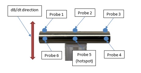
The gradient induced heating testing was performed using the methods specified in the gradient induced device heating clause of ISO/TS 10974 with the same exposure conditions as the simulations. The test object was placed inside a phantom filled with a tissue simulating gel solution (1.2 S/m HEC) perpendicular to the dB/dt field. Using a research gradient magnetic field generator, the object was exposed to a changing magnetic field of 42T/s RMS using a sine waveform with a frequency of 1750Hz for a total of 15 minutes per exposure. Fiber optic temperature probes were placed across the surface of the cylindrical test object, including the hotspot identified in the modeling results. The approximate temperature probe placements on the object under test are shown in Figure 2. These temperature probes were used to monitor and record the test objects’ temperature response throughout the test exposure with temperature measurements being recorded at least once every second. In addition, one probe was also placed near the edge of the test phantom to monitor background temperature changes.
Results
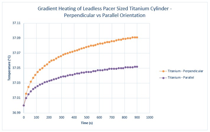
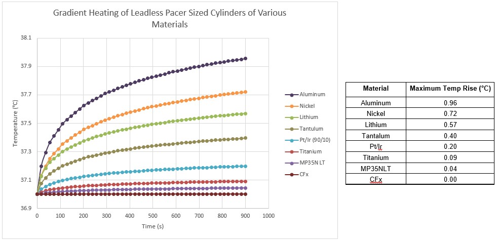
An initial set of simulations were conducted on a Titanium cylinder in both the parallel and perpendicular orientations shown in Figure 1. The results of the simulations, seen in Figure 3, show that the perpendicular orientation is worst case, generating the largest amount of heating.Once the worst-case orientation was determined (perpendicular), simulations were then conducted for the remaining materials in that orientation. The simulation results are shown in Figure 4. As can be seen in this figure, the resultant temperature rise for all of the materials modeled was less than 1°C, with Aluminum, Nickel and Lithium generating the highest heating.
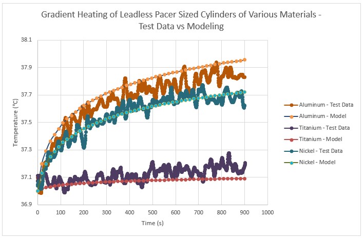
To validate the simulation results, benchtop testing was conducted on three representative materials. The results of the benchtop testing are shown in Figure 5. As can be seen in this Figure, the validation test results match well with the modeling results.
Discussion/Conclusions
As seen in the results section above, the modeling and benchtop testing of the leadless pacemaker sized objects resulted in temperature rises which were all less than 1°C, with the largest temperature rise seen in the aluminum test object. This object serves as a conservative surrogate for leadless pacemakers as the entire test object is constructed from the worst-case heating material, whereas leadless pacemakers are constructed from a composite of materials which will not all contribute to heating. In general, a temperature rise less than 2°C is considered to be clinically insignificant2. As such, the risk of leadless pacemaker gradient induced device heating is negligible and assessments for this hazard per ISO/TS 10974 may not be necessary.Acknowledgements
No acknowledgement found.References
1. ISO/TS 10974, 2018, "Assessment of the safety of magnetic resonance imaging for patients with an active implantable medical device" ISO, Geneva, Switzerland, www.astm.org.
2. Fda.gov, 2021, “Testing and Labeling Medical Devices for Safety in the Magnetic Resonance (MR) Environment, Guidance for Industry and Food and Drug Administration Staff” [online] Available at: https://www.fda.gov/regulatory-information/search-fda-guidance-documents/testing-and-labeling-medical-devices-safety-magnetic-resonance-mr-environment
Figures