4825
Design of a permanent magnet for a 0.55 T tabletop MRI1Department of Radiology, Medical Physics, Medical Center University of Freiburg, Faculty of Medicine, University of Freiburg, Freiburg, Germany, 2High Field MR Center, Center for Medical Physics and Biomedical Engineering, Medical University of Vienna, Vienna, Austria
Synopsis
Optimize the shape of pole shoes of a 0.55 T permanent magnet to increase the homogeneity of the main magnetic field in a region of interest.
Introduction
Multiple low-cost tabletop MRI scanners for education and research prototyping have been developed [1-7]. With major advances in the receive chain and the related gain in SNR, low field MRI systems regained a lot of attention recently. Lower field systems are especially advantageous in MRI-guided surgery with metal device and efficient imaging in high-susceptibility regions [8]. For contrast related experiments and testing of high-performance imaging technologies a low-cost tabletop scanner would be advantageous to have a 0.55T magnet. In this work, a 0.55 T permanent magnet is designed by minimizing the inhomogeneity of the main magnetic field in a region of interest (ROI). Moreover, the deformation due to Lorentz forces is analyzed and its effects on the inhomogeneity is explored.Methods
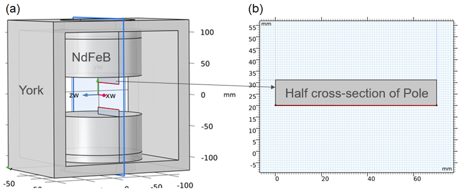
Our magnet design consists of NdFeb N52 discs, yoke and pole shoes and is symmetric about y =0 plane. This design is similar to a tabletop system designed by the MGH group [1] and is shown in Fig 1.a. The thickness of a NdFeb discs was increased to 60 mm to achieve a strength of 0.55 T. In order to minimize the inhomogeneity of the magnetic field in the spherical ROI of 7.5 mm radius, shapes of poles were optimized. As marked in red color in Fig 1, the boundary of the half cross-section of a pole is expressed as a 4th-order polynomial and the coefficients of the polynomial are defined as design variables in the optimization. The magnetic field distribution of the magnet was calculated using Comsol (COMSOL AB, Stockholm, Sweden). Based on the symmetry of the magnet, only one-eighth of the magnet needs to be simulated. The optimization problem was solved by the function fmincon using MATLAB (Mathworks, Natick, MA, USA).After the optimization, the deformation of the optimized magnet due to Lorentz forces was simulated using the structure mechanics module of Comsol. The magnetic field of the deformed magnet was calculated and the effects of the deformation on the inhomogeneity of main magnetic field was assessed.
Results and Discussion
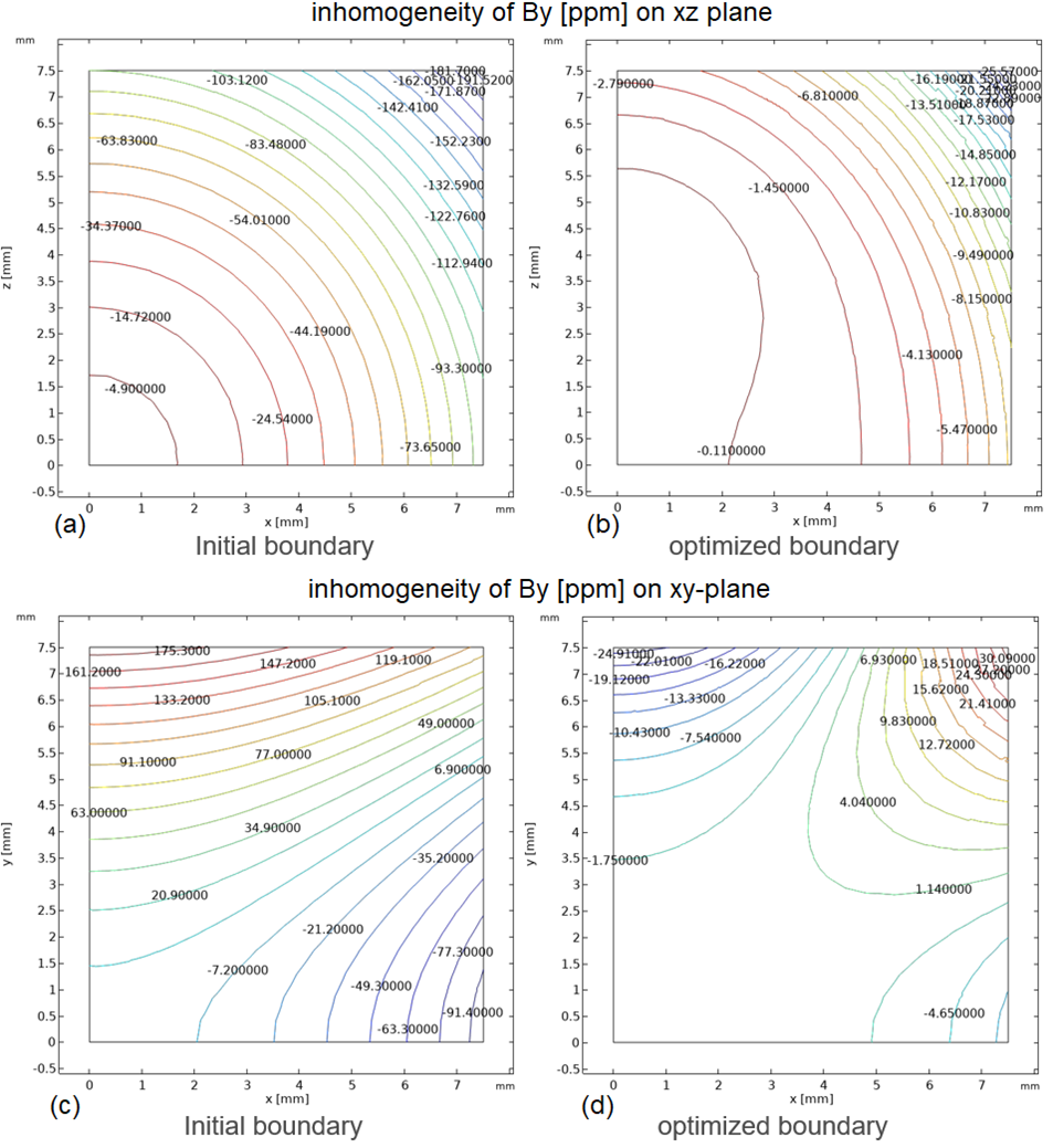
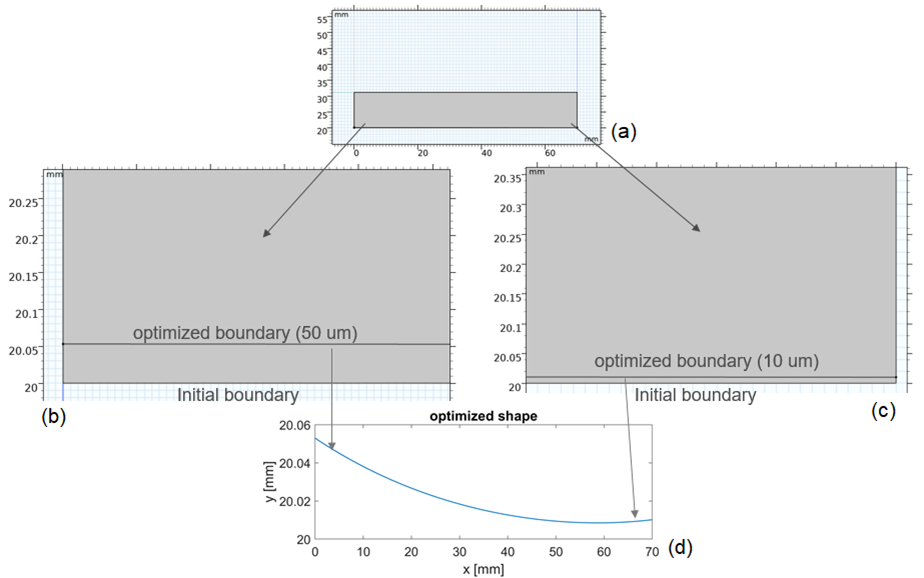
Figure 2 shows the comparison of field inhomogeneities in the unit of ppm between the initial and optimized boundaries. The maximum field inhomogeneity for the initial boundary is around 182.3 ppm in the ROI. Compared to the initial boundary, using the optimized boundary leads to the reduction of the maximum field inhomogeneity by more than 6.9 times, i.e. 26.36 ppm.Figure 3 presents the initial and optimized boundary of the pole. As seen, the initial boundary is located at y = 20mm plane. Compared to the initial boundary, the optimized boundary has around 50 µm variation along y-axis at x =0 and around 10 µm variation at x =70 mm. Such small variations may lead to two problems: The first one is the fabrication of the pole. A 5-axis Computerized Numerical Control (CNC) milling machine with 5µm accuracy may help to address this issue. The second one is whether the deformation of the magnet due to Lorentz force has a big influence on the field homogeneity or not.
Figure 4 displays the deformation of one-eighth optimized magnet. As depicted, the deformation for the pole part occurs mainly in the direction of the y coordinate axis. The lower surface of the pole sinks by about 4 µm. Based on this result, the pole, the NdFeb disc and the upper part of yoke for the optimized magnet were shifted downwards by 4 µm to form a deformed magnet.
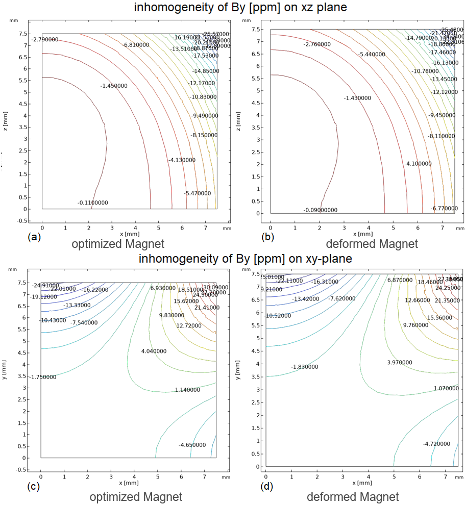
Figure 5 depicts the comparison of field homogeneity between the optimized and deformed magnet. The maximum field non-uniformity of the deformed magnet increases only by a factor of 1.0034 compared to that of the optimized magnet. The fabrication of the optimized magnet using advanced manufacturing techniques will be investigated in future step.
Conclusions
A shape optimization of magnet poles allows one to increase the homogeneity of a permanent magnet. The field strength of 0.55 T seems feasible for a tabletop MRI system. Preliminary results suggest that the magnet can be designed to achieve the field uniformity of around 26 ppm.Acknowledgements
The project was funded by the German Federal Ministry of Education and Research under grant number 13GW0356B. The author is responsible for the content of this publication.References
[1] Cooley el al. Design and implementation of a low-cost, tabletop MRI scanner foreducation and research prototyping, J Magn Reson. 2020;310:106625.
[2] S.M. Wright et al., A desktop magnetic resonance imaging system, Magn.Reson. Mater. Phys. Biol. Med. 13 (3) (2001) 177–185.
[3] N. Iita et al, Development of a compact MRI system formeasuring the trabecular bone microstructure of the finger, Magn. Reson. Med.57 (2) (2007) 272–277.
[4] C.A. Michal, Low-cost low-field NMR and MRI: Instrumentation and applications, J Magn Reson. 2020;319:106800.
[5] O'Reilly T et al., Three-dimensional MRI in a homogenous 27 cm diameter bore Halbach array magnet. J Magn Reson. 2019;307:106578.
[6] P.C. McDaniel et al, The MR Cap: a single-sided MRI system designed for potential point-of-care limited field-of-view brain imaging. Magn Reson Med. 2019;82:1946
[7] R. Kowal et al, Comparison of SNR between a low-field (0.26T) Tabletop-MRI and a clinical high-field (3T) scanner, in: Proc. 2021 Annu. Meet. ISMRM, p. 3119, 2021.
[8] Campbell-Washburn et al. Opportunities in Interventional and Diagnostic Imaging by Using High-Performance Low-Field-Strength MRI, Radiology 2019;293:384.
Figures