4798
A Comprehensive MR Fingerprinting Development Kit (MRFDK)1Siemens Healthcare GmbH, Erlangen, Germany, 2Siemens Healthcare s.r.l, Milan, Italy, 3Siemens Medical Solutions USA Inc., Chicago, IL, United States, 4Department of Radiology, Case Western Reserve University, Cleveland, OH, United States
Synopsis
Magnetic Resonance Fingerprinting (MRF), as an approach for multi-parametric, quantitative imaging, imposes new paradigms for sequence design in terms of optimized signal encoding and dictionary matching. In this work, we present a novel comprehensive framework and tool chain for rapid and efficient MRF prototyping. Key concepts are modularization and abstraction of the MRF experiment related to spin-physics, spatial encoding, and scanner hardware.
Background
The original MRF method1 has triggered a variety of different implementations of the fundamental concept for numerous quantitative mapping applications, such as exploring and optimizing the encoding of T1 and T2 relaxation, magnetization transfer effects, diffusion, flow, etc. A clear promise of the MRF approach is the vast new parameter space in terms of signal encoding as compared to conventional MR imaging methods. However, this is also a challenge for development, prototyping and scanner deployment, since existing MR sequence programming environments do not easily support the dedicated requirements, such as linking signal encoding to a certain parameter space via a dictionary. While clinical studies require the ability to efficiently roll out the MRF experiment on different scanner platforms, the repeatability and portability of a specific MRF experiment at scanners with different hard- and software, and ultimately from different manufacturers, present a particular challenge. This work addresses these needs by establishing a dedicated MRF programming framework for efficient development, rapid prototyping, and easy scanner deployment.Methods
Sequence & Software Design: We introduce two central data structures - the MRF dictionary and the MRF sequence definition - featuring generic interfaces allowing access from different development environments (e.g., C++, Matlab, Python) and provide a comprehensive tool chain linking the data structures to mandatory components such as spin-physics simulation and scanner control.The MRF dictionary contains all relevant information for the signal matching procedure. The data structure is flexible in terms of parameter dimensions and ranges such that it can be customized for specific quantitative applications. The MRF sequence definition specifies the complete MRF experiment in a generic way in terms of sequence timing and spin-physics, such that it serves as a consistent input for both, the dictionary calculation and the execution of the sequence on the scanner.
As a fundamental concept the MRF experiment is prescribed by a stream of WTX and WRX sections (figure 1). WTX denotes a "Warp (W) followed by an RF-Pulse (TX)", WRX denotes a "Warp (W) followed by a readout echo center (RX)", where "Warp" represents a gradient-only sequence section. In its simplest form Warp realizes 0th order gradient moments between two gradient amplitudes, but for advanced MRF techniques any gradient-based manipulation of the spins could be realized.
Notably, the MRF sequence definition does not yet specify all details required for really executing the sequence such as the spatial encoding, segmented acquisition schemes, etc., which is realized by a separate highly modular execution engine. This separation allows running a prescribed MRF experiment with different spatial encoding modules (e.g., 2D/3D, cartesian/radial/spiral, etc.) and on different scanner platforms simply by replacing the according modules in the execution engine. During execution of the MRF sequence the spatial encoding gradients are inserted on the fly; pre-phasing and rewinding of trajectory start/end positions in k-Space are automatically handled by the warp module.
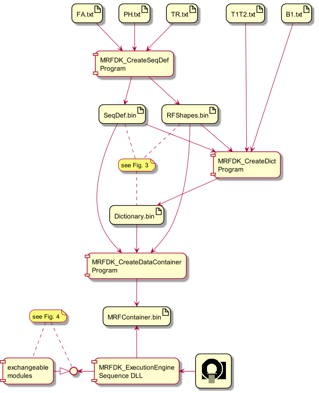
The toolchain for a typical MRF experiment is depicted in figure 2. The flexibility of the underlying software design is detailed in the figures 3 and 4.
Validation: The newly developed software is validated against an existing reference which is currently represented by a 2D spiral encoding, single-shot, slice-by-slice FISP MRF experiment with 1500 echoes2. A conventional implementation of the reference is executed by the scanner software dumping the instructions for gradients, RF, receiver and oscillator on a 100ns raster. This is compared against the implementation using the new development framework. Ultimately, the sequences are executed on a 3T scanner (MAGNETOM Vida, Siemens Healthcare, Germany) and both, the raw measurement data and the parameter maps, are compared.
Results & Discussion
The software framework for MRF development has been implemented and successfully validated against a reference implementation.Figure 5 illustrates how a sequence definition data structure translates to a generic sequence prescription diagram, which is the actual input for dictionary calculation and scanner execution, and finally the full acquisition scheme from the execution engine. Note the stringent separation between abstract sequence prescription by only a few parameters, that are required to define the MRF signal evolution, and the actual translation to a scanner executable, which is delegated to the execution engine. The MRF experiment can be changed in various ways, only by editing the sequence definition parameters but without the need for conventional sequence programming.
Although the sequences were implemented in a completely different manner, both the reference and the new version produce identical results when evaluating the scanner instruction dump and the measured data.
Conclusion
We introduced and implemented an "MRF Development Kit" (MRFDK) prototype and validated it.A novel MRF sequence definition concept allows feeding both, the dictionary calculation, and the scanner execution engine, reducing the overhead and vulnerability due to redundant or inconsistent data.
The generic part of the MRF experiment is contained in plain data structures and configuration files for rapid and flexible prototyping without programming efforts, and moderate programming efforts for extending the framework functionality if needed.
The explicit separation of the MRF encoding model from the actual execution engine opens the potential for running the same MRF experiment on different scanner platforms which is a key requirement, e.g., for establishing scanner independent, quantitative biomarkers.
Acknowledgements
No acknowledgement found.References
1. Ma D, et al. Magnetic resonance fingerprinting. Nature. 2013;495(7440):187-192. doi:10.1038/nature11971
2. Yokota Y, et al. Acceleration of 2D-MR fingerprinting by reducing the number of echoes with increased in-plane resolution: a volunteer study. MAGMA. 2020;33(6):783-791. doi:10.1007/s10334-020-00842-8
3. Stupic KF, et al. A standard system phantom for magnetic resonance imaging. Magn Reson Med. 2021; 86: 1194– 1211. https://doi.org/10.1002/mrm.28779
Figures

Graphical representation of the creation of the WTX/WRX-stream concept needed for both, the execution of the MRF sequence and the computation of the MRF dictionary. E.g., a 2D spiral FISP MRF sequence with 1500 FISP kernels would consist of 3001 of such blocks per slice, the first WTX block representing the inversion pulse and then a pair of WTX plus WRX for every of the 1500 FISP kernels.


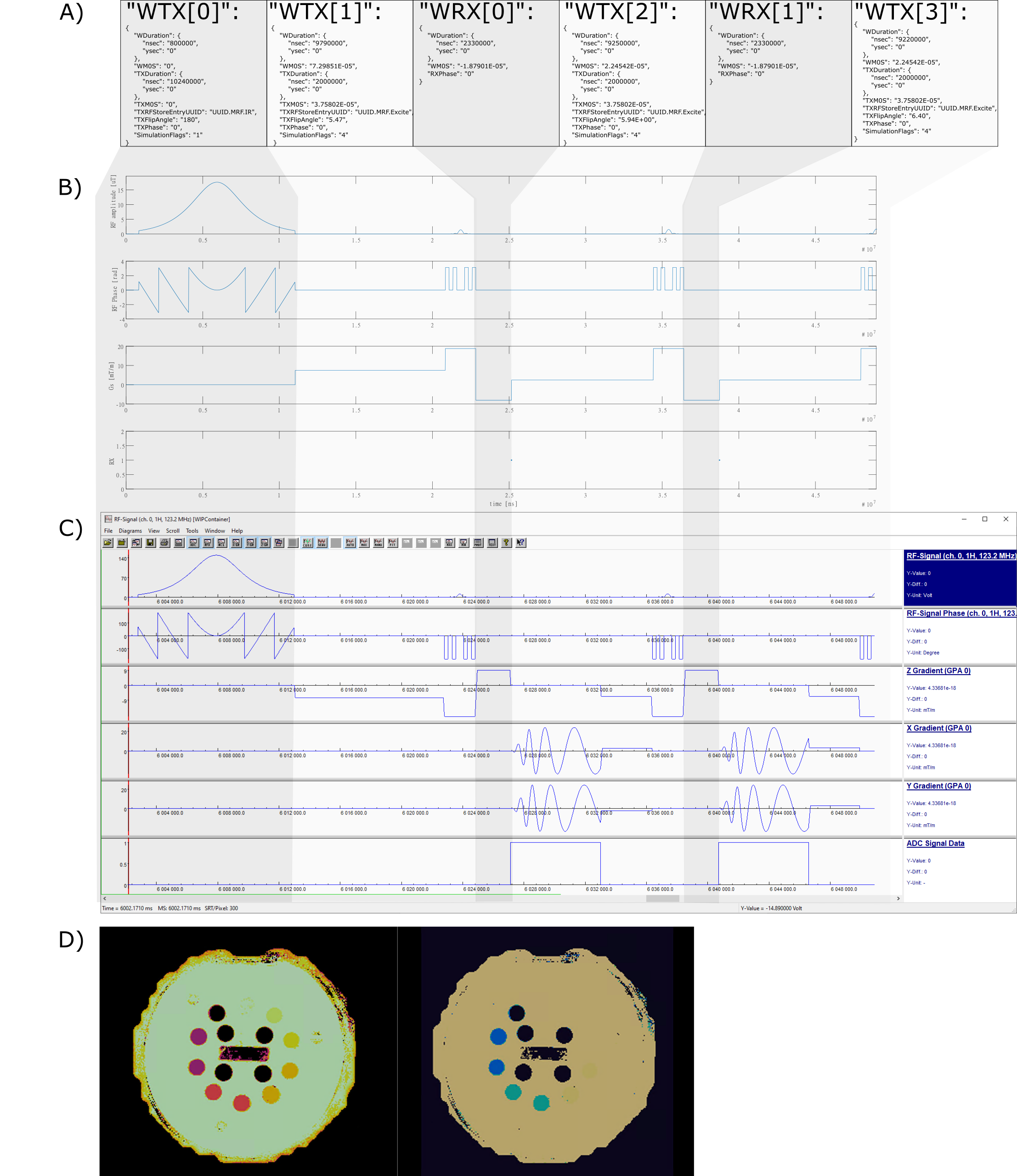
A) The actual MRFDK sequence definition in JSon format exactly as read and processed by the execution engine for creating the sequence shown in C.
B) Matlab-plot of the sequence definition without details of spatial encoding and warp blocks.
C) Screenshot of a sequence simulation tool showing the result of the execution engine presented as timing diagram for RF-pulses (abs/phase), gradients and readouts.
D) Resulting T1 and T2 maps of the NIST MRF Phantom3 acquired by the new sequence.