4646
Design and Construction of an 8-channel transceiver coil array for Rat imaging at 9.4T
Feng Du1,2, Nan Li1,2, Xing Yang1,2, Baogui Zhang3, Xiaoliang Zhang4, Xin Liu1,2, Hairong Zheng1,2, and Ye Li1,2
1Lauterbur Research Center for Biomedical Imaging, Shenzhen Institutes of Advanced Technology, Chinese Academy of Sciences, Shenzhen, China, 2Key Laboratory for Magnetic Resonance and Multimodality Imaging of Guangdong Province, Shenzhen, China, 3Brainnetome Center, Institute of Automation, Chinese Academy of Sciences, Beijing, China, 4Department of Biomedical Engineering, State University of New York, Buffalo, NY, United States
1Lauterbur Research Center for Biomedical Imaging, Shenzhen Institutes of Advanced Technology, Chinese Academy of Sciences, Shenzhen, China, 2Key Laboratory for Magnetic Resonance and Multimodality Imaging of Guangdong Province, Shenzhen, China, 3Brainnetome Center, Institute of Automation, Chinese Academy of Sciences, Beijing, China, 4Department of Biomedical Engineering, State University of New York, Buffalo, NY, United States
Synopsis
The development of RF coils for the ultrahigh-field(UHF) MRI system is greatly significant for biomedical research as it determines imaging performance. In this work,an 8-channel transceiver array was designed and constructed for UHF MRI at 9.4 T to take full advantage of the benefits provided by higher field strengths. The phantom and in vivo studies were performed on preclinical 9.4 T MRI system to verify the proposed tansceiver performance. The results proved the ability of the proposed 8-channel transceiver array to obtain high signal-to-noise ratio (SNR) and high-spatial resolution MR images at 9.4T and indicated the potentiality for UHF MRIapplications.
Introduction
Ultrahigh magnetic field (UHF) magnetic resonance animal imaging is a valuable technique in biomedical research characterized by enhanced signal-to-noise ratios (SNRs) and spatial resolution of MR images [1-4]. Ultrahigh field 9.4T MRI has been shown to provide superior resolution and anatomical details. As the critical component for realizing the high sensitivity provided by UHFs, the design of RF coils is great significant. However, the required high operating frequency at UHFs makes the design of highly efficient radio frequency (RF) transmit or receive coils technically challenging, especially there are inherent difficulties in the design of multi-channel RF array coils due to their structural complexity. The aim of this work is to design and construct an 8-channel transceiver coil array for UHF MRI at 9.4 T. The phantom and in vivo studies performed on the Bruker preclinical 9.4 T MRI system to verify the performance of the proposed 8-channel coil and the potentiality for ultra-high field MRI applications.Method
An 8-channel transceiver RF coil was developed for a preclinical 9.4 T (Bruker BioSpec 94/30) MRI scanner, as shown in Fig. 1. The outer 83cm-diameter cylindrical frame was wrapped by eight-loop transceiver coils that resonate at both 400.3MHz for 1H imaging. And the loop dimension was 20 mm×35 mm with a width 4 mm. To generate circularly polarized B1+ fields, the transceiver array was driven through eight output signals generated by their interface circuits (Fig. 2) with equal magnitude but 45°phase increments, corresponding to the azimuthal position of the coils. The high power output signal from the RF power amplifier was divided into eight equal parts by a 1:8 power splitter which consisted of three quadrature hybrids and four 1:2 power dividers. Their relative phase shift was achieved by coaxial cable segments with different lengths.The geometric spacing of the eight-element coil is adjusted to minimize the coupling between adjacent and next-adjacent loops. A cylindrical saline phantom made of pvc with a diameter of 55 mm and a length of 100 mm was employed, consisting of 55.4 g/L NaCl, 1085 g/L Sucrose. A 2-D flash sequence sequence with the following parameters was used to acquire images of the signal: TR/TE = 2000 ms/4 ms, flip angle = 60°, field of view (FOV) = 100 ×100 mm2, slice thickness = 1 mm, and matrix size =96 ×96. The flip angle is set to 0 to obtain noise. The 9.4T standard birdcage coil was utilized as a reference and was tested with the same protocol. The T1_FLSH_2D sequence was used to scan the rat’s body. The scan parameters were as follows:TR/TE = 1500 ms /5.5 ms, flip angle = 30°, field of view (FOV) = 80*80 mm2, slice thickness = 1 mm, and matrix size =320*320, averages=4, time=40 min. To calculate the B1+ distributions in the rat abdomen, the T1_FLSH_2D sequence was applied to obtain single-angle and double-angle images.RESULT
The relevant amplitude and phase offset of four outputs generated by the interface circuit for all operating frequencies were well balanced with the absolute amplitude and phase offsets standard deviations were smaller than 0.4 dB and 2 degree, respectively (Fig. 2(b)). Therefore, after sending these outputs to drive the coil array with our properly designed azmuthmal positions, a homogeneous circular polarized B1+ field can be expected. The complete measured s-parameter matrix of the proposed 8-channel RF coil was shown in Fig. 3 (a), which shows S-parameters confirming that all the coils were well tuned and were sufficiently matched to 50Ω (<-20 dB), with the arithmetic maximum of reflection coefficient no larger than -15dB for all coils. The isolation between any two loops no smaller than -14.8 dB. The noise correlation matrix was measured from noise images,as shown in Fig. Fig. 3 (b). The maximum mutual coupling coefficient is less than 0.36, and the average value is 0.15, which demonstrated good decoupling between coil channels. The images in transverse plane for the proposed 8-channel rat coil array and the standard birdcage coil are shown and the corresponding SNR maps are depicted in Fig. 3. The SNR variation along the white dotted line makes clear that the SNR of the proposed 8-channel rat coil array along the left-right direction was greatly superior to that of the standard birdcage coil in the periphery of the phantom and slightly worse than that of the standard birdcage coil in the central region. Fig. 5 shows rat abdomen images were acquired with the 8-channel rat coil acquired in the transverse, sagittal, and coronal plane, orthogonal to the rat anatomy. And the corresponding planes calculated B1+ maps acquired in vivo show that the array produced a uniform transmit field in the abdomen region of the transverse plane with no outstanding issues in homogeneity.Conclusion
In this study,an 8-channel transceiver coil array was designed and fabricated for animal magnetic resonance imaging at 9.4T. The results of phantom and in vivo studies verified the performance of the proposed 8-channel coil and the potentiality for ultra-high field MRI applications. Potentially, the coil performance can be improved by expanding the size of the individual channel and simultaneously employing decoupling techniques.Acknowledgements
This work was supported in part by Guangdong Province grants 2018B030333001;National Key R&D Program of China, 2021YFE0204400; the Strategic Priority Research Program of Chinese Academy of Sciences (Grant No. XDB25000000); city grant RCYX20200714114735123.References
[1] Wang C, Li Y, Wu B, Xu D, Nelson S, Vigneron D, Zhang X, “A Practical Multinuclear Transceiver Volume Coil for in vivo MRI/MRS at 7 T”, Magn. Reson. Imag., vol. 30, no. 1, pp. 78-84, 2012. [2] Pang Y et al., “A Dual-tuned quadrature volume coil with mixed λ/2 and λ/4 microstrip resonators for multinuclear MRSI at 7 T”, Magn. Reson. Imag., vol. 30, no. 2, pp. 290-298, 2012. [3] Hu X, Chen X, Liu X, Zheng H, Li Y, Zhang X, “Parallel Imaging Performance Investigation of an 8-channel Common-Mode Differential-Mode (CMDM) Planar Array for 7T MRI”, Quant Imag. Med. Surg., vol. 4, no. 1, pp. 33-42, 2014. [4] Feng Du et al., “Numerical Simulation and Evaluation of a Four-Channel by Four-Channel Double-Nuclear RF Coil for 1H MRI and 31P MRSI at 7T,” IEEE Trans. Magn., vol. 54, no. 11, pp. 1-4, 2018. Digital Object Identifier: 10.1109/TMAG.2018.2856529Figures
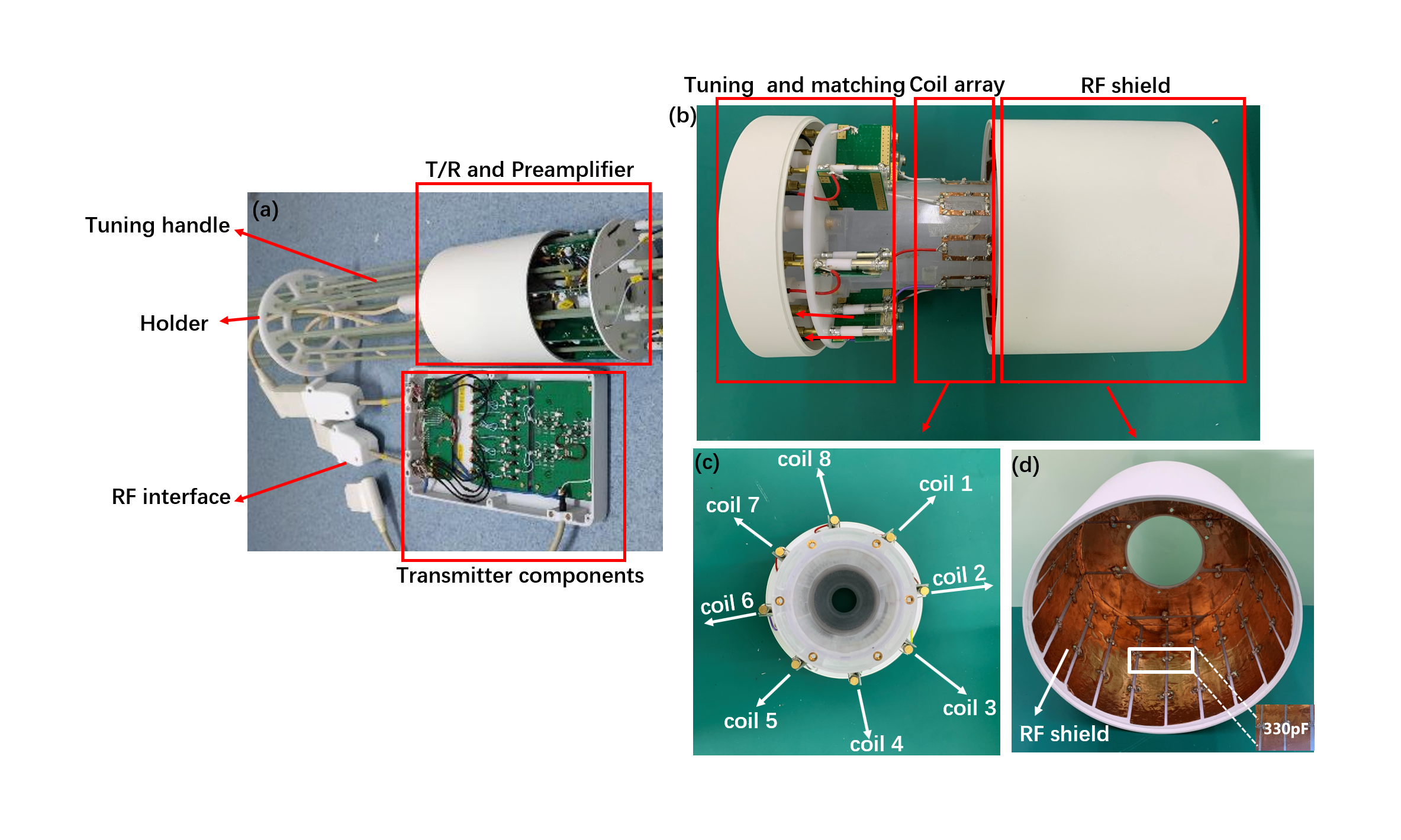
Fig. 1. Photograph of the constructed 8-channel
transceiver array system.
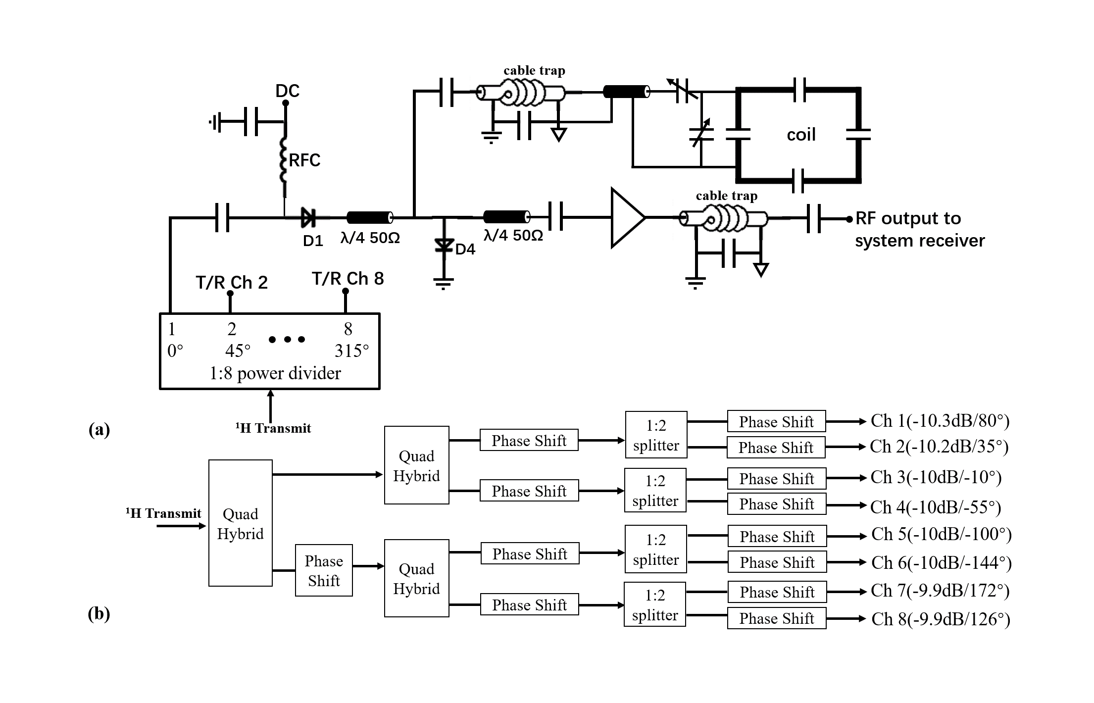
Fig. 2. (a), Flattened two-dimensional
schematic diagram of the eight-channel coil array and interface. For
simplicity, a single coil was shown. RFC, radiofrequency choke (3.9μH). The
status of the DC bias is forward in transmission and reverse in receive mode. A
detailed block diagram of the proton power divider and amplitude and phase
offset of eight output are shown in (b).
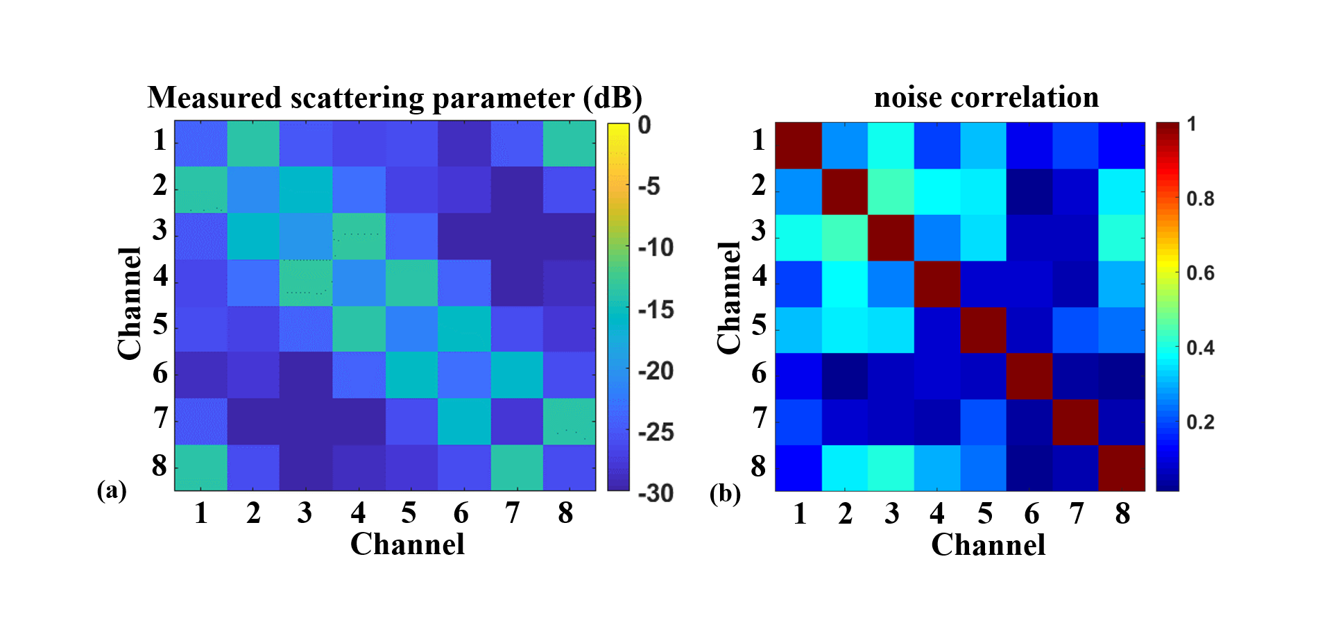
Fig. 3. S-parameter matrix
of the 8-channel transceiver array(left) and the acquired noise correlation matrix(right).
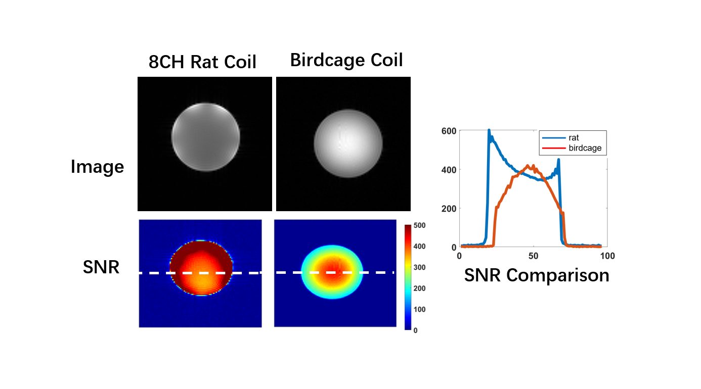
Fig. 4.
Images were acquired with array and birdcage (first raw), respectively.
The SNR map of proposed 8-channel carotid coil (left) and standard birdcage
coil (right) in the transverse plane. A comparison of SNR along the white
dotted line (from left to right) between the two coils. The array provided
similar signal-to-noise ratio (SNR) in the center of the phantom and gains in
the periphery compared with the standard birdcage.
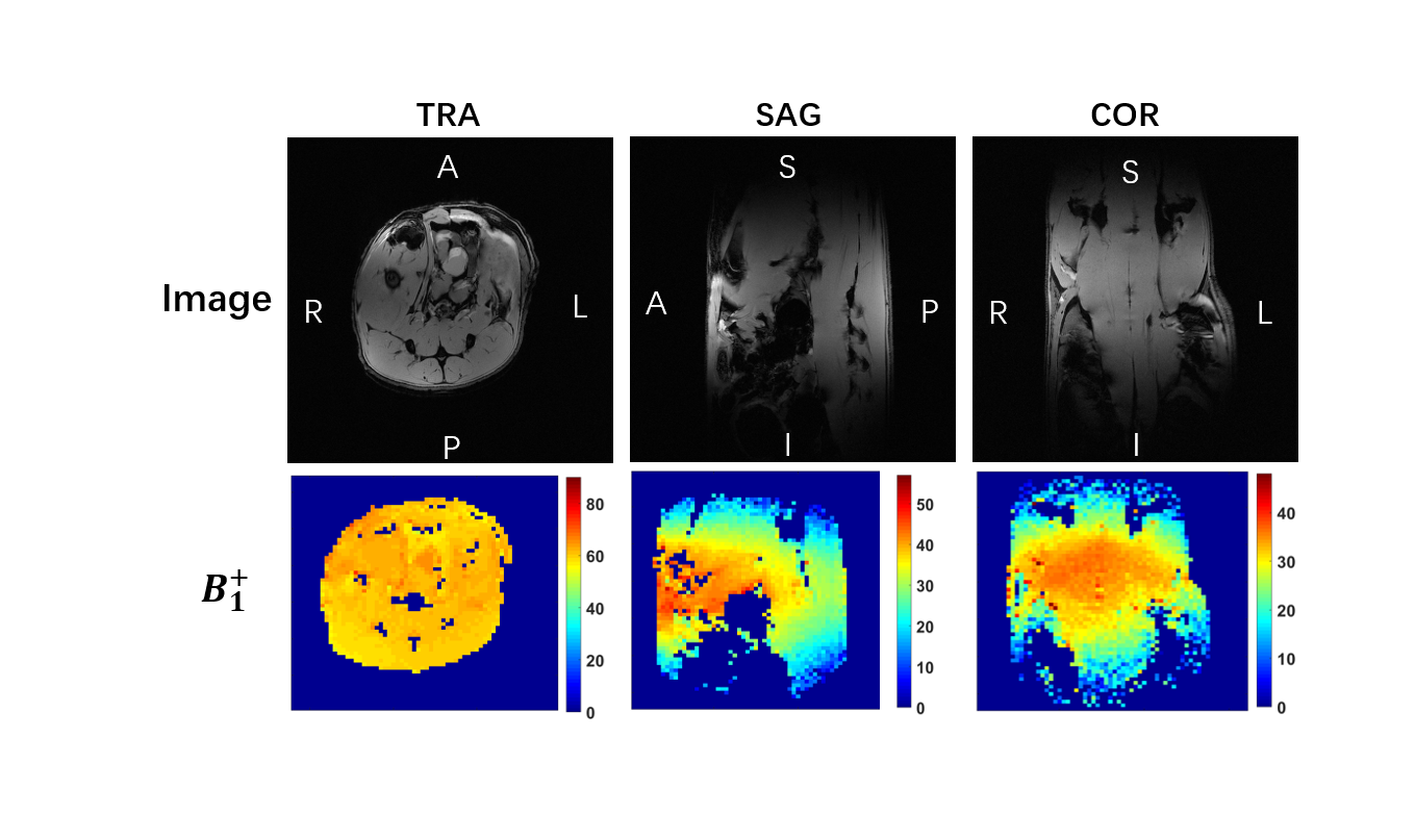
Fig.
5. Transverse, sagittal, and coronal
views of abdomen anatomical images (first raw), and the corresponding B1+
distribution map (second raw). The B1+ maps show that the array provided a uniform
transmit field in the abdomen region.
DOI: https://doi.org/10.58530/2022/4646